
Product Short Description
Product Brief Introduction
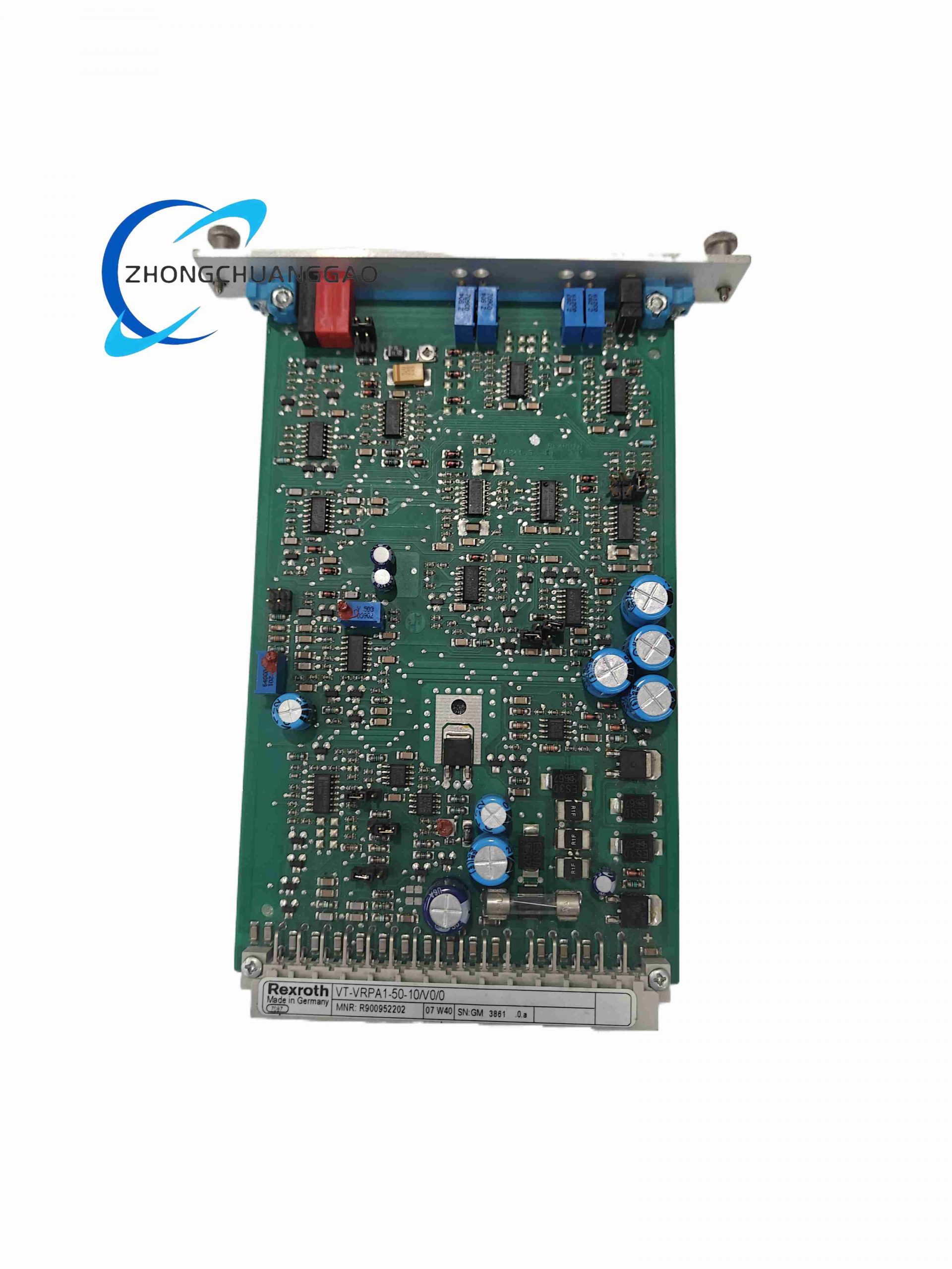
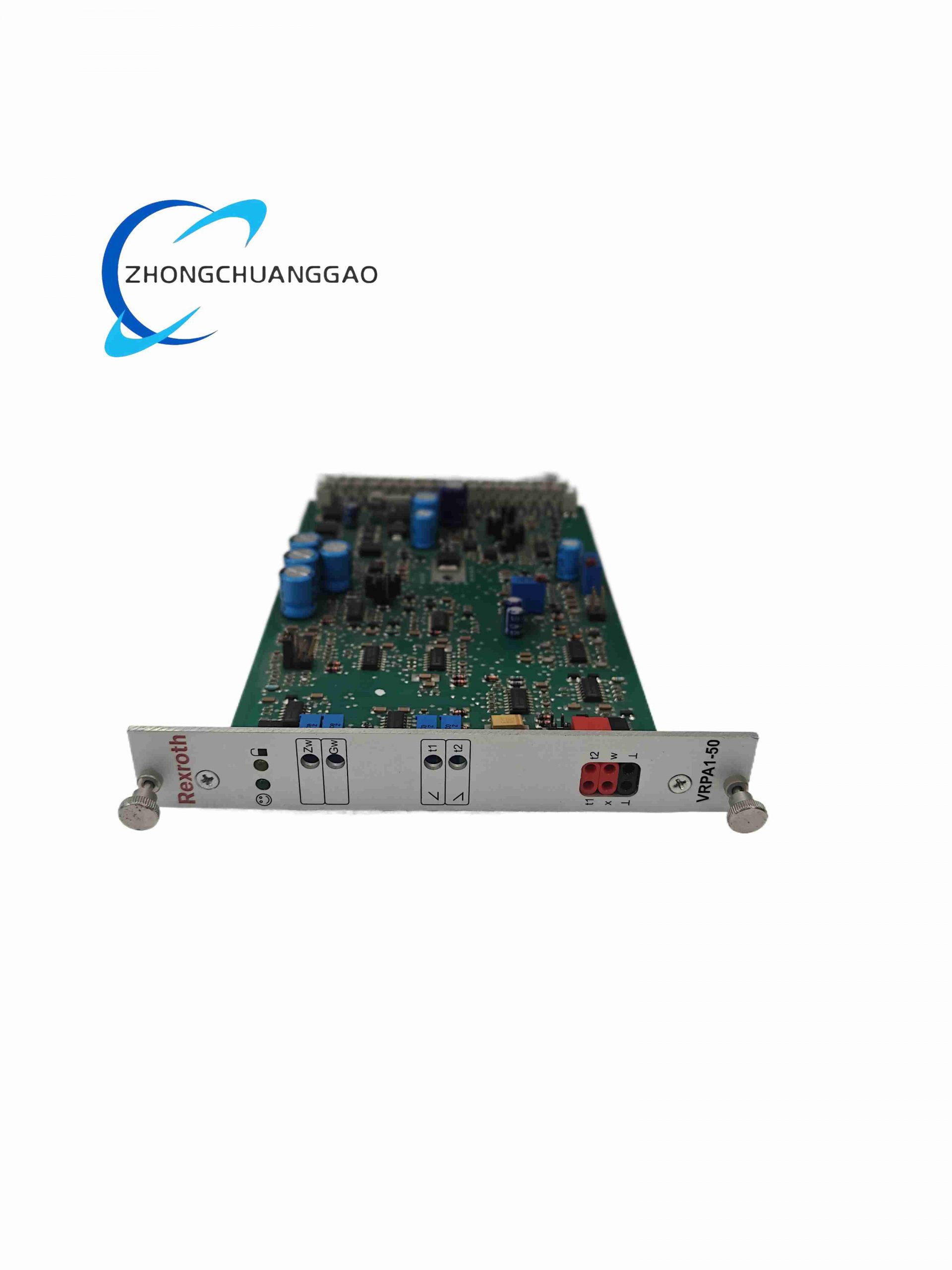
This DIN rail plug-in analog amplifier belongs to Bosch Rexroth VT-VRPA1 series, designed for closed-loop position control of proportional pressure valves and flow control valves with built-in LVDT position transducers. It converts standard analog command signals into modulated solenoid driving current, executes PID closed-loop regulation, and provides configurable acceleration/deceleration ramps to achieve smooth hydraulic motion control. It adopts clocked pulse-width modulation output stage, supports multiple signal input formats, and integrates full fault diagnosis circuit for hydraulic servo system safety monitoring.
Description
Core Technical Performance Parameters
- Supply Voltage: 24 V DC nominal, operating range 21–30 V DC
- Total Power Consumption: Max 30 W
- Max Solenoid Driving Current: 2.2 A continuous
- Input Command Signal Modes (selectable via jumpers):
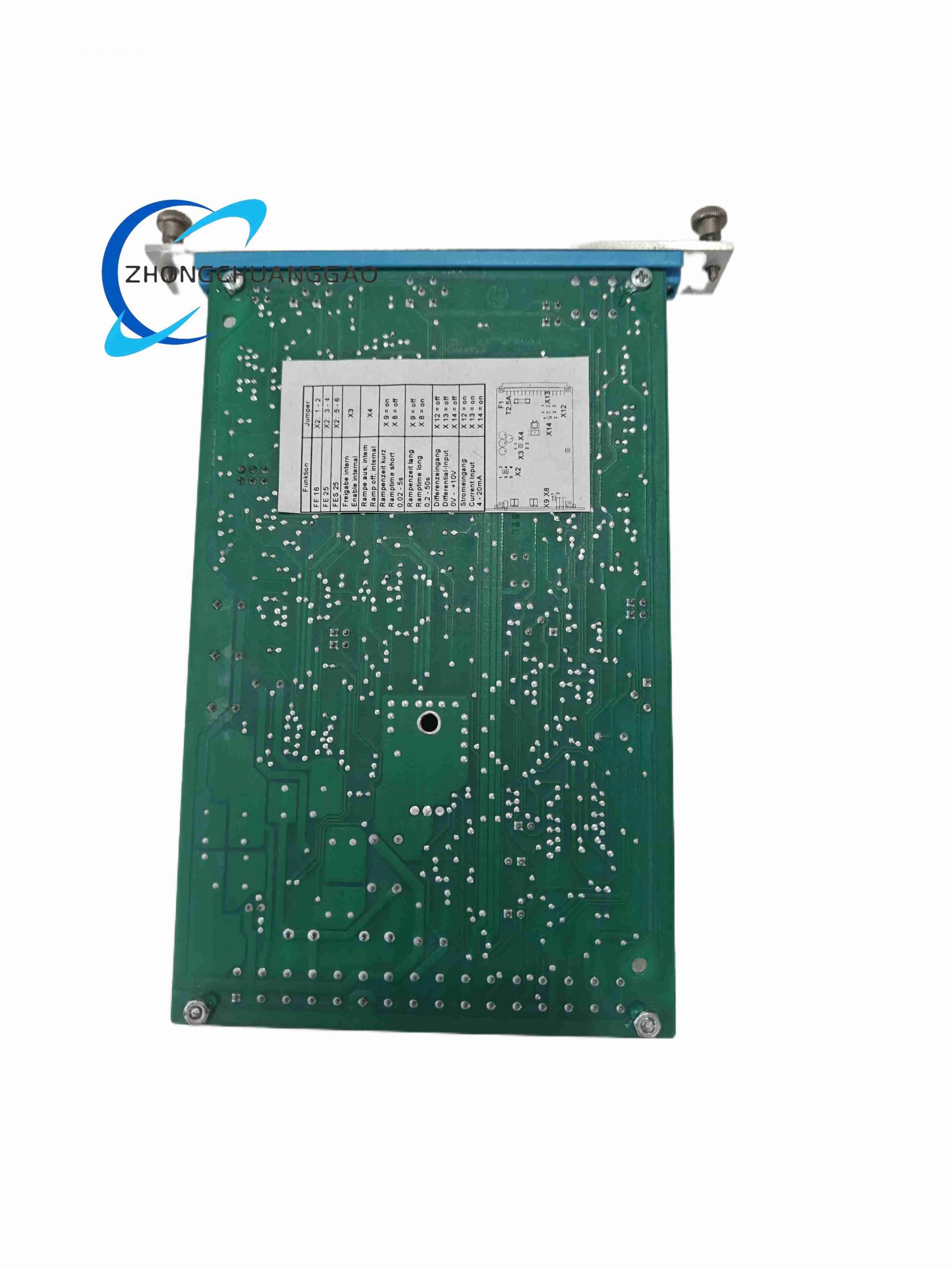
- Voltage: 0–6 V, 0–9 V, 0–10 V
- Current: 0–20 mA, 4–20 mA
- LVDT Excitation Frequency: 2.5 kHz ±10% regulated oscillator
- Ramp Time Two Range Switchable:
Short ramp: 0.02 s – 5 s
Long ramp: 0.2 s – 50 s
- PID Adjustable Parameters on Front Panel Trim Pots: Zero Offset, Gain Sensitivity, Acceleration Ramp, Braking Ramp
- Fault Signal Output: 24 V DC max 100 mA switch output for system alarm
- Operating Ambient Temperature: 0 °C to +50 °C
- Storage Temperature: -20 °C to +70 °C
- Overall Dimensions: 182 mm Depth × 20 mm Width × 128.4 mm Height
- Net Weight: 0.15 kg
- Connector Standard: 32-pin DIN 41612 Form D male industrial connector
Function & Feature Highlights
- Full closed-loop PID position control for proportional valve spool position
- Short-circuit protection for solenoid output and LVDT feedback wiring open-circuit detection
- Separable internal/external ramp control logic for flexible motion profile programming
- Regulated ±9 V reference power supply for external position potentiometer (25 mA load capacity)
- LED status indicators: Power Ready, Feedback Fault, Low Supply Voltage Alarm
- Plug compatibility with legacy Rexroth VT5011, VT5012, VT5062–VT5066 amplifier modules
- Isolated measurement test sockets for real-time setpoint and actual position signal reading
- Enable inhibit digital input for machine safety interlock cut-off
Working Principle
- The controller receives analog setpoint signal from PLC or motion controller, compared with LVDT spool position feedback signal to generate deviation error value.
- Internal PID circuit calculates correction output, then drives PWM clocked power stage to output variable current to proportional valve solenoid.
- LVDT oscillator continuously excites valve position sensor, converts mechanical spool displacement back to analog feedback voltage for closed-loop correction.
- Ramp timing circuit filters sudden signal jumps to avoid hydraulic shock; fault monitoring circuit continuously scans wiring continuity and supply voltage, triggers digital alarm output upon abnormal status.
Material & Structural Composition
- Main Housing: Flame-retardant black PA66 plastic DIN rail housing, anti-vibration rib structure
- PCB Substrate: FR4 high-temperature fiberglass circuit board with tin-lead free plating
- Power Components: High-frequency MOSFET power switching tubes, sealed film adjustment potentiometers
- Connector Housing: Glass fiber reinforced thermoplastic, gold-plated contact pins for anti-corrosion
- Heat Dissipation: Integrated aluminum alloy heat sink strip on power output zone
Installation Requirements
- Standard 35 mm top-hat DIN rail vertical cabinet mounting, vertical installation only (horizontal mounting forbidden for heat dissipation)
- Maintain minimum 20 mm vertical clearance above and below the module for air convection cooling
- Wiring rule: Power zero line and control zero line must be short bridged when cable distance below 1 m; separate ground wiring for control zero if cable exceeds 1 m length
- Maximum wiring distance between amplifier and proportional valve LVDT sensor shall not exceed 10 meters with shielded twisted pair cable
- Shield cable single-end grounding at amplifier cabinet side only, floating ground at valve side to eliminate ground loop interference
Application Scenarios
- CNC machine tool hydraulic servo axes (clamping, feed, spindle tension control)
- Metal forming hydraulic presses (stamping, bending, injection molding machine clamping unit)
- Marine hydraulic valve remote proportional pressure regulation
- Industrial robot hydraulic joint closed-loop control
- Wind turbine hydraulic pitch adjustment systems
Operation & Maintenance Precautions
- Do not apply over 30 V DC supply voltage, reverse polarity input will permanently damage internal power circuit
- All jumper configuration changes must be completed under power-off state
- Avoid installing in cabinet areas with direct oil mist, water splash or corrosive gas; install IP54 sealed cabinet if working in harsh workshop environment
- Regularly clean dust accumulation on PCB heat sink every 6 months to prevent overheating protection trigger
- LVDT feedback cable must use dedicated shielded twisted wire; ordinary unshielded cable will cause control oscillation and position drift
- Ramp time adjustment range must match machine mechanical inertia; overly short ramp will generate hydraulic impact and pipeline vibration
Reviews
There are no reviews yet.