
Product Short Description
Product Brief Introduction
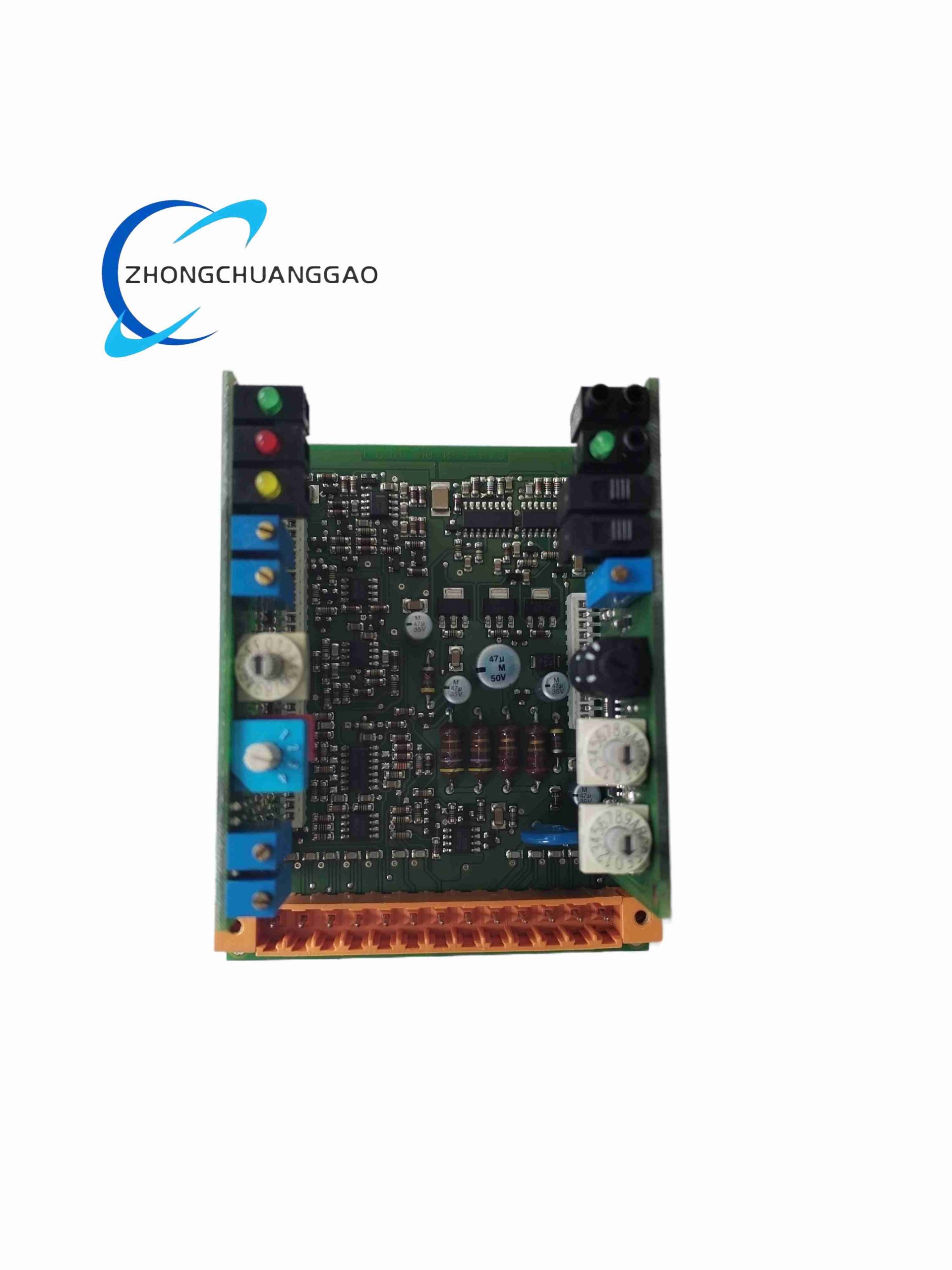
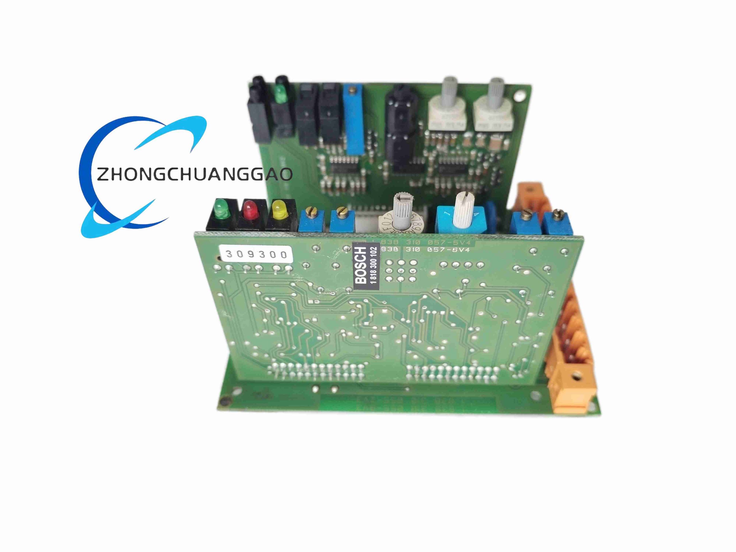
This is a high-precision microcontroller-based hydraulic servo amplifier under Bosch Rexroth VT control platform, dedicated to closed-loop position and velocity control of integrated-electronics proportional/servo valves. It adopts standard 100×160mm Eurocard double-layer PCB design, supports multi-group parameter storage and rapid parameter switching via digital encoding inputs, built-in independent ramp generator, cable break diagnosis and short-circuit protection circuits, widely used in precision hydraulic positioning axes for industrial machinery.
Description
Core Technical Specifications
- Power Supply: 24 VDC, tolerance +40% / -5%, power consumption ≤ 28W
- Command Input Signals: ±10V analog voltage, 4–20mA analog current, binary digital parameter switching input
- Feedback Signal Interface: LVDT, RVDT, potentiometer position transducer, tachometer speed feedback
- Control Algorithm: PT1 closed-loop position control; PI closed-loop velocity control (with tachometer accessory)
- Parameter Storage: Non-volatile flash memory, maximum 16 independent parameter sets
- Ramp Function: Separately adjustable rising/falling ramp time range 0.01–10s
- Control Accuracy: Steady-state positioning error ≤ ±0.05% full stroke
- Operating Temperature: -25°C ~ +60°C
- Storage Temperature: -40°C ~ +85°C
- Insulation Grade: Input/output isolation 500 VAC, EMC compliance EN 61000-6-2 / EN 61000-6-3
- Dimensions: 160mm (H) × 100mm (W) × 26mm (D), net weight 0.21kg
- Protection Class: IP20 (indoor cabinet installation only)
Functional Features
- Independent enable hardware input, interlock protection to cut valve output under fault status
- Real-time cable break detection for position feedback wiring, trigger fault alarm signal once open circuit occurs
- All analog/digital interfaces adopt full short-circuit protection, reverse polarity anti-damage circuit
- Front panel reserved dedicated test points for on-site debugging without disassembly wiring
- Optional switchable compensation jump function to eliminate hydraulic zero drift deviation
- Digital binary coded input allows one-click switching of stored motion parameter groups without PLC program modification
- Separate adjustable acceleration/deceleration ramps to avoid mechanical impact during axis fast switching
- Built-in fault message output relay contact for upper system fault signal collection
Working Principle
- Upper PLC transmits motion command value via ±10V voltage or 4–20mA current analog channel to the amplifier’s summing circuit; digital input selects pre-stored PID gain/ramp parameter group from flash memory.
- The built-in microcontroller compares command value with real-time position feedback signal from valve transducer to generate deviation signal.
- Deviation signal passes PT1 position regulation loop to output proportional drive current to valve proportional magnet; when equipped with tachometer feedback, PI velocity closed-loop is superimposed to suppress speed fluctuation under variable load.
- Ramp generator limits the rate of command value change to realize smooth axis acceleration and deceleration; diagnosis circuit continuously monitors wiring continuity and output short-circuit state, cuts drive output and triggers alarm once abnormal signal detected.
Structure & Material Composition
- Main Housing: Flame-retardant black ABS plastic DIN rail clamping shell, anti-aging, anti-electromagnetic interference
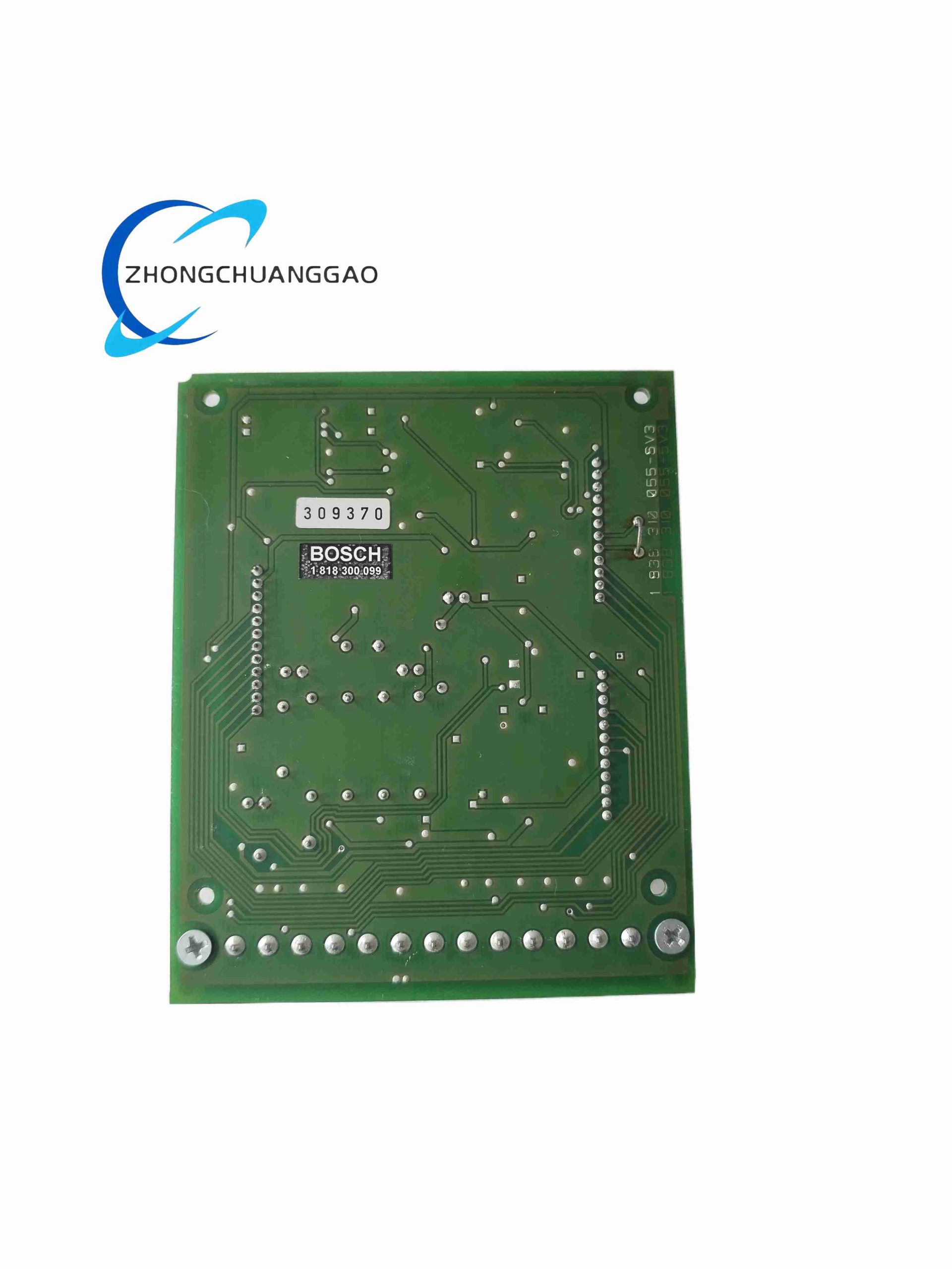
- Core Circuit Board: Double-sided FR4 high-temperature resistant PCB, surface conformal coated acrylic insulation layer to resist humidity and dust corrosion
- Internal Electronic Components: Industrial-grade wide-temperature microcontroller, precision metal film resistors, low-drift operational amplifiers, solid-state relay fault output module
- Terminal Block: Copper gold-plated screw terminals, anti-oxidation, support 0.5–2.5mm² stranded shielded cable
- Front Panel: Silk-screen circuit block diagram, LED status indicator lights (power, enable, fault, cable break), metal test pin sockets
Installation Requirements
- Standard 35mm DIN rail snap mounting inside IP20 industrial control cabinet, vertical or horizontal installation allowed
- Maintain minimum 20mm ventilation gap above and below module for heat dissipation; cannot stack heat-generating power modules adjacent
- Power wiring must use twisted shielded copper cable, cable length ≤ 50m; add external 1000μF smoothing capacitor if supply voltage fluctuation exceeds ±10%
- Signal wiring of command and feedback must adopt separate double-shielded twisted cable, separate routing from power cable to avoid EMC interference
- Cabinet ground wire connected to module housing ground terminal, ground resistance ≤ 1Ω to eliminate signal noise
- Torque of terminal screw tightening controlled at 0.8–1.2 N·m to prevent terminal loose contact
Application Scenarios
Precision hydraulic injection molding machines, metal sheet stamping equipment, material fatigue test benches, CNC hydraulic bending machines, hydraulic press positioning axes, aerospace component test equipment, automated welding fixture hydraulic drive systems.
Operation & Maintenance Precautions
- Cut off 24V power supply completely before wiring, debugging or module replacement to avoid circuit burnout
- Do not connect ±10V voltage signal to 4–20mA current input channel, which will permanently damage internal sampling circuit
- Regularly check front panel LED fault indicators; cable break alarm mostly caused by damaged shielded feedback wire or loose transducer terminal
- If positioning zero drift occurs, enable compensation jump function via front panel potentiometer calibration
- Avoid operating environment with oil mist, corrosive gas or condensation; regular compressed air dust cleaning every 6 months
- Do not disassemble PCB shell without authorization; internal conformal coating will lose protection after shell removal
Reviews
There are no reviews yet.