
Product Short Description
Product Brief Introduction
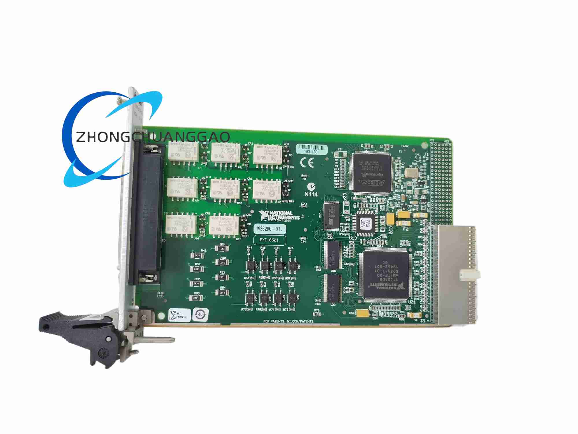
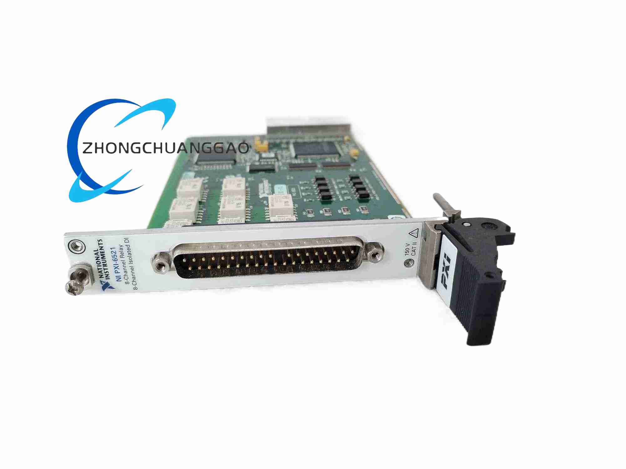
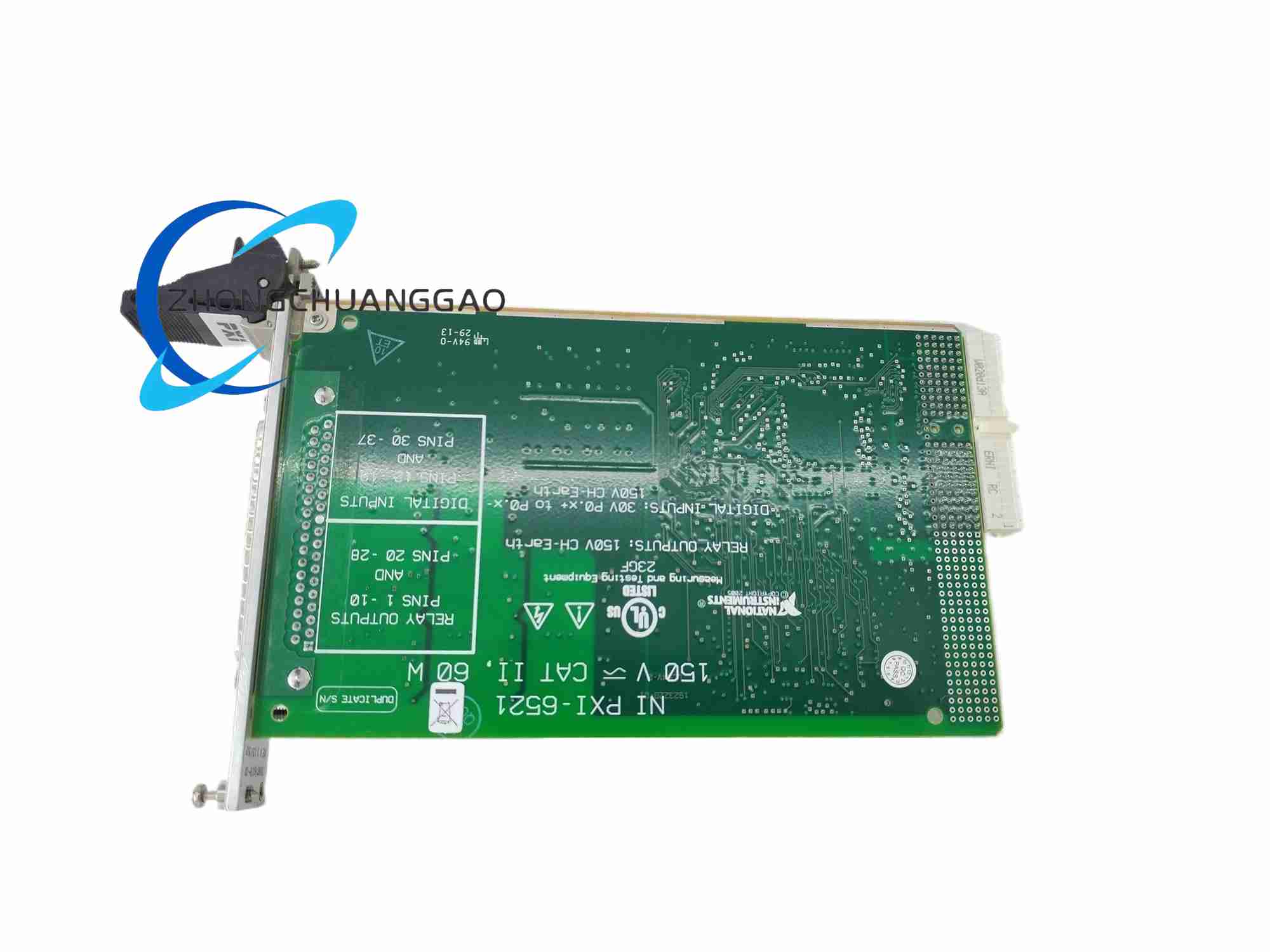
Industrial-grade isolated digital I/O PXI module built for harsh factory automation, equipment interlock, and safety-critical control applications. Equipped with full galvanic isolation between input channels, output relays, and PXI bus backplane to eliminate ground loop interference and protect host measurement hardware from industrial high-voltage transients. Features programmable watchdog safety logic, user-defined power-up relay states, digital input noise filtering, and hardware change detection for real-time industrial signal monitoring
Description
Core Technical & Performance Specifications
- Channel Configuration Breakdown
- Digital Input Channels: 8 galvanically isolated differential sink/source input channels
- Digital Relay Output Channels: 8 mechanical non-latching relay outputs (3 SPDT Type-C relays, 5 SPST Type-A relays)
- Digital Input Electrical Specifications
- Input Voltage Operating Range: ±30 VDC per channel
- Maximum Transient Voltage Tolerance per Input Channel: 150 VDC peak
- Channel-to-Channel Isolation Rating: 60 VDC continuous
- Channel-to-Backplane Bus Isolation Rating: 150 VDC continuous
- Channel-to-Chassis Ground Isolation Rating: 150 VDC continuous
- Input Logic Type: Positive logic; high voltage level = logic active state
- Relay Output Electrical Specifications
- Maximum Relay Switching Power Rating: 60 W DC / 60 VA AC per relay channel
- Maximum Switching Voltage: 150 VDC / 150 VAC RMS
- Continuous Maximum Switching Current: 2 A per relay channel at 0–55 °C ambient temperature
- Relay Operating Mechanical Lifespan: ≥10,000,000 no-load switching cycles; ≥100,000 full-rated load switching cycles
- Onboard Control & Timing Specifications
- Programmable Digital Input Filter: Software-configurable low-pass noise filter to suppress industrial contact bounce and electromagnetic noise
- Hardware Change Detection Logic: Interrupt generation on any digital input state transition for real-time event response
- I/O Watchdog Safety Timer: User-programmable timeout period; automatically switches all relay outputs to predefined safe state if host software communication failure occurs
- Programmable Power-Up / Power-Down Relay States: User-settable default relay open/closed condition during chassis power-on or power-loss events; state transition response time 400 ms maximum
- Physical & Environmental Specifications
- Form Factor: Standard single-width 3U PXI module
- Operating Temperature Range: 0 °C to 55 °C
- Storage Temperature Range: -40 °C to 85 °C
- Relative Humidity Rating: 10%–90% non-condensing
- Module Front Panel Connector: Keyed locking D-SUB connector (keyed housing prevents incompatible cable misconnection for enhanced operational safety)
Key Functional Features
- Multi-layer full galvanic isolation architecture separating digital input field signals, mechanical relay output load circuits, and PXI backplane control bus to block ground loops, voltage transients, and industrial EMI noise
- Integrated I/O watchdog fault safety system to protect controlled industrial equipment during host PC software crash, communication dropout, or chassis power fluctuation events
- Independent programmable digital input filtering to eliminate mechanical switch contact bounce, high-frequency industrial motor noise, and transient voltage spike interference
- Hardware-level change detection interrupt functionality to trigger immediate host software processing when any digital input channel signal state changes
- Fully user-customizable power-up and power-failure relay output states to define fail-safe interlock conditions for safety-critical manufacturing machinery
- Keyed locking front-panel signal connector to prevent accidental miswiring with incompatible industrial cable assemblies, reducing field wiring fault risks
- Full NI DAQmx driver software support, compatible with LabVIEW, LabWindows/CVI, Python, C#, C++ programming environments for custom industrial control application development
- Complete channel-to-channel independent signal routing; no shared signal ground between individual input and output channels
Working Principle
- Digital Input Signal Path Working Principle
- External industrial field voltage signals (0–±30 VDC) connect to differential isolated input channel terminals
- Each input channel contains independent optocoupler galvanic isolation circuitry to separate field-side high-voltage signals from low-voltage PXI bus control logic
- Analog input signal passes through software-configurable RC low-pass digital filter circuit to suppress high-frequency noise and mechanical contact bounce artifacts
- Filtered digital logic level signal feeds to onboard FPGA logic chip, which continuously monitors input state and triggers hardware change detection interrupts upon signal transitions
- Mechanical Relay Output Signal Path Working Principle
- Onboard FPGA control logic receives relay actuation commands transmitted over the PXI backplane bus from the host controller
- Control logic drives low-power relay coil driver circuits to energize or de-energize individual mechanical relay coils
- Energized relay coils physically actuate internal mechanical switch contacts to open or close the external industrial load circuit path
- Isolation barrier between relay coil low-voltage control side and high-current load contact side prevents industrial load circuit transients from damaging onboard FPGA and PXI bus hardware
- Watchdog Safety System Working Principle
- Onboard independent hardware timer continuously receives periodic reset heartbeat signals from host control software via PXI bus communication
- If heartbeat reset signals cease for longer than user-programmed timeout duration, watchdog hardware immediately triggers a global relay state reset sequence
- All relay outputs automatically switch to preconfigured user-defined safe open/closed state to shut down hazardous industrial equipment loads during software or communication failure events
Structure & Material Composition
- Module Main PCB: UL94 V-0 flame retardant FR4 multi-layer printed circuit board with gold-plated signal traces and connector pads
- Galvanic Isolation Components: High-breakdown voltage optocoupler ICs with reinforced isolation die packaging for input channel isolation
- Mechanical Relay Components: Epoxy-sealed non-latching electromechanical relays with copper alloy switch contact terminals, nickel-plated relay coil pins, high-temperature plastic relay housing
- Front Panel Assembly: Die-cast aluminum alloy front panel with powder-coated matte black corrosion-resistant surface, engraved channel identification text, mounting retention screw hardware
- Signal Connector Assembly: Keyed D-SUB locking connector with glass-filled nylon flame retardant plastic housing, gold-plated contact pins, threaded locking fasteners for cable retention
- Onboard Control Logic: Industrial-grade Xilinx FPGA chip, low-noise linear voltage regulator ICs, surface-mount RC filter network components, high-temperature ceramic decoupling capacitors
Installation Mandatory Requirements
- Mechanical Module Installation Rules
- Insert module only when target PXI chassis main AC power supply is fully disconnected to avoid backplane short-circuit damage
- Slide module fully into selected PXI chassis peripheral slot until front panel makes flush contact with chassis slot faceplate; tighten both left and right front-panel retention screws evenly to secure full electrical contact between module and backplane slot connectors
- Install filler panels on all unused empty chassis slots to maintain uniform chassis forced-air cooling airflow
- Electrical Field Wiring Installation Rules
- Separate low-voltage digital input signal wiring and high-current relay output load wiring into isolated cable bundles to eliminate cross-channel electromagnetic crosstalk interference
- For all external field wiring connections, implement dedicated protective overcurrent fuses on every relay output load circuit to prevent short-circuit load currents from damaging onboard relay switch contacts
- Connect chassis protective earth ground via chassis rear-panel ground screw to establish reliable ESD and EMI shielding reference potential
- Only utilize factory-matched keyed signal cable assemblies compatible with the module’s keyed D-SUB front panel connector; non-keyed generic D-SUB cables cannot physically lock into the connector housing
- Software Driver Installation Rules
- Install NI DAQmx driver suite matching the host operating system version prior to chassis power-up and module detection
- Launch NI MAX configuration software after chassis power-on to execute automated module hardware self-test, verify channel isolation integrity, and assign system hardware resource addresses
- Configure watchdog timeout duration, digital input filter cutoff frequency, and power-up relay safe states within NI MAX before deploying custom industrial control application code
Strict Usage Precautions
- High-Voltage & Electrical Safety Precautions
- Never connect external field signals exceeding the module’s rated maximum isolation voltage limits (150 VDC peak channel-to-ground) to input or output channels; overvoltage transients will permanently destroy onboard optocoupler isolation components and mechanical relay assemblies
- All high-current relay output load circuits must include external freewheeling diode suppression components when switching inductive industrial loads (solenoid valves, motor contactors, electromagnetic actuators) to absorb inductive voltage flyback transients and extend relay mechanical service lifespan
- Disconnect all external field wiring cables from the module front panel connector before performing module removal, reconfiguration, or chassis maintenance procedures
- Thermal Operating Precautions
- Maintain chassis cooling fan operation at adequate speed to keep module operating temperature within the 0 °C to 55 °C rated range; continuous operation above 55 °C ambient temperature accelerates mechanical relay contact oxidation, reducing rated switching cycle lifespan
- Avoid stacking multiple high-power relay output modules in adjacent chassis slots without adequate forced-air cooling; concentrated heat buildup between adjacent modules creates thermal throttling risk
- Mechanical & Lifespan Precautions
- Mechanical relay internal switch contacts degrade with each load switching cycle; strictly adhere to rated maximum switching power and current specifications to avoid premature relay contact welding or burnout
- Prevent physical mechanical shock or vibration exposure to the module during operation; excessive vibration causes intermittent relay contact disconnection and permanent internal PCB solder joint fracture damage
- ESD Protection Precautions
- Wear certified ESD grounding wrist strap and connect strap ground lead to chassis protective earth ground screw before handling the module or modifying field wiring connections
- Store spare modules in original factory antistatic shielding bags when not installed inside a powered PXI chassis
Target Application Scenarios
- Factory automation assembly line machine interlock safety control systems
- Industrial test bench equipment power relay switching and digital sensor state monitoring
- Automotive electronic component end-of-line functional test systems
- Semiconductor manufacturing equipment safety interlock and wafer handling machine control
- Energy power distribution cabinet auxiliary status signal monitoring and circuit breaker control
- Medical device manufacturing test systems requiring galvanically isolated signal channels for electrical safety compliance
- Building HVAC industrial control panel digital input sensor monitoring and fan/valve relay actuation
Reviews
There are no reviews yet.