
Product Short Description
Product Introduction
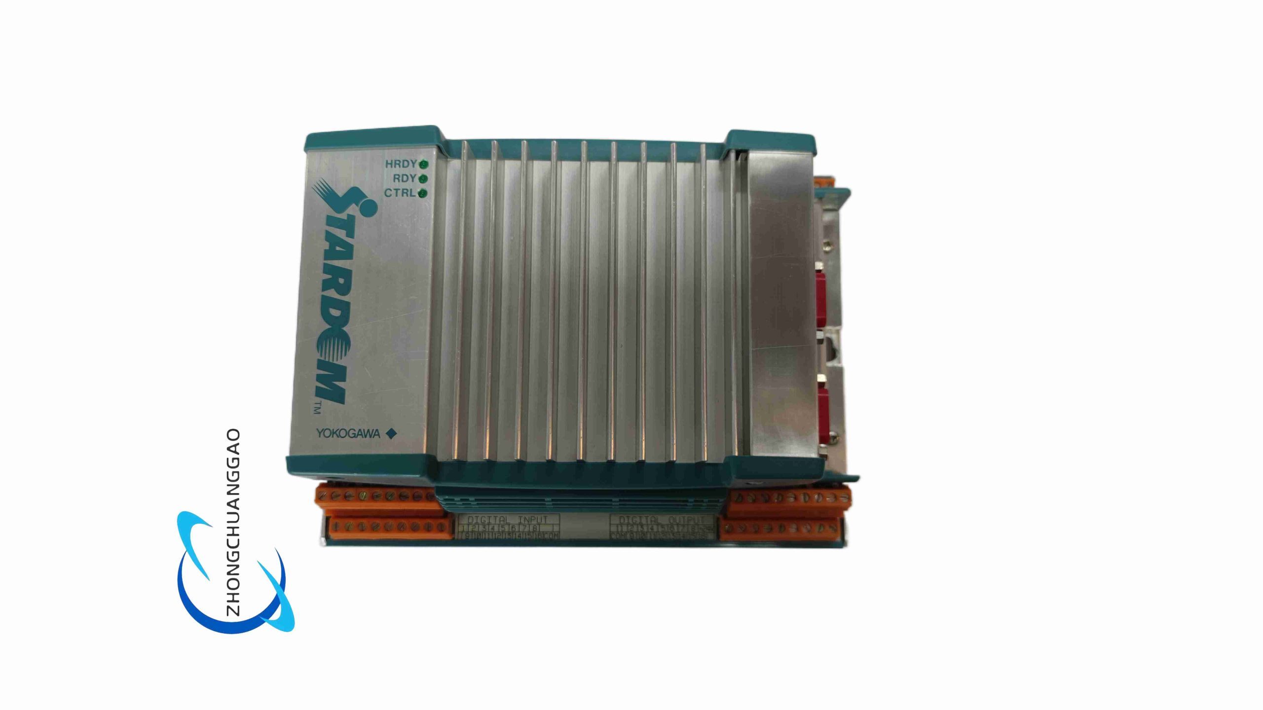
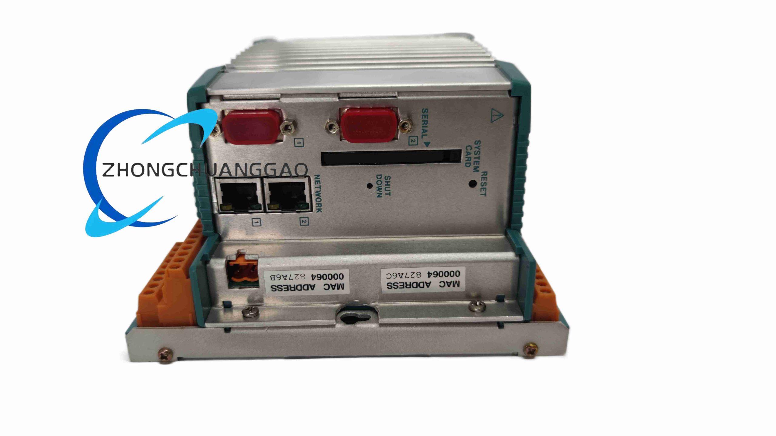
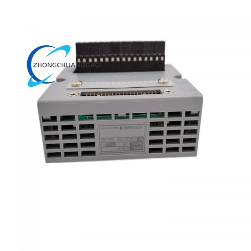
This is a compact DIN rail mounted microprocessor-based signal isolation transmitter dedicated for industrial temperature measurement. It converts weak thermocouple or RTD resistance temperature signals into standard 4-20mA DC analog output signals, with full galvanic isolation between input, output and power supply circuits to eliminate ground loop interference in complex industrial wiring environments.
Description
Core Technical Specifications & Performance Parameters
- Input Signal Types
- Thermocouple Input: K, E, J, T, R, S, B, N standard thermocouple types
- RTD Resistance Input: Pt100, JPt100 platinum resistance temperature sensors
- Standard Output Signal: 4mA ~ 20mA DC two-wire loop-powered analog signal
- Measurement Accuracy: ±0.1% of full measurement span
- Signal Response Time: 90ms fast conversion response
- Galvanic Isolation Strength: 1500V AC dielectric isolation between input/output/power loops
- Power Supply Range: 12V DC ~ 45V DC two-wire loop power supply
- Operating Temperature Range: -40℃ ~ +85℃ wide industrial temperature range
- Physical Dimensions: 72mm(H) × 24mm(W) × 127mm(D), ultra-narrow 24mm width to save cabinet installation space
- Net Weight: 160g
- EMC Compliance Standard: IEC 61326-1 industrial electromagnetic compatibility
- Explosion-Proof Certifications: ATEX, FM, CSA, TIIS, IECEx, NEPSI intrinsic safety approval for hazardous area installation
Function & Feature Highlights
- Universal multi-type temperature input support, single module compatible with all mainstream industrial thermocouple and RTD sensors
- High-precision microprocessor signal processing circuit, software programmable zero/span calibration without physical potentiometer adjustment
- Complete galvanic three-way isolation (input, output, power supply) to completely eliminate ground loop noise and common-mode signal interference
- Built-in sensor burnout detection function; automatically output fixed upper/lower limit current signal when thermocouple wire breaks or RTD circuit open-circuits
- Compact ultra-narrow 24mm width DIN rail mounting design, maximizes electrical cabinet internal space utilization rate
- Full intrinsic safety explosion-proof certification, suitable for installation in Zone 0/1/2 hazardous flammable gas industrial environments
- Front panel terminal wiring design, convenient on-site wiring, terminal screw clamping structure for stable wire fixation under equipment vibration
- Software configurable via Yokogawa VJ77 PC parameter setting tool; users can modify measurement range, sensor type and burnout logic on-site without replacing hardware
Working Principle
The NFJT100-S10E transmitter adopts a two-wire loop power supply architecture; the 4-20mA output loop simultaneously supplies working power for the internal microprocessor circuit. Weak temperature-dependent resistance or millivolt voltage signals from field thermocouple/RTD sensors are first filtered by an analog low-pass filter circuit to remove high-frequency industrial electromagnetic noise. The filtered analog signal is converted to digital data via a high-resolution ADC chip, then processed by the embedded microprocessor with built-in temperature compensation algorithms to eliminate cold-junction thermocouple measurement error. The calibrated digital temperature value is converted back to a linear 4-20mA DC analog output signal via a DAC circuit, transmitted to remote DCS/PLC analog input modules through two-wire shielded cable. The internal isolation transformer circuit blocks DC common-mode voltage between field sensor loop and control room cabinet power loop to prevent measurement drift caused by ground potential difference.
Material Composition & Structural Features
- Housing Material: Die-cast lightweight aluminum alloy shell, anti-corrosion anodized surface treatment, high mechanical shock resistance
- Internal Circuit Board: SMT surface mount industrial PCB, isolated transformer isolation components, precision metal film calibration resistors
- Mechanical Structure: Standard 35mm DIN rail snap-on mounting base, spring buckle fixed structure for fast installation and disassembly; front panel equipped with screw-type wiring terminals with anti-loosening spring washers
- Protection Structure: Fully sealed internal circuit compartment, IP30 front panel dustproof protection grade; terminal compartment separated from main circuit to prevent wiring dust contamination
Installation Requirements
- Mounting Method: Snap onto standard 35mm DIN mounting rail inside indoor electrical control cabinet only
- Wiring Specification: Use shielded twisted pair cable for field temperature sensor input wiring; shield layer single-end grounded inside control cabinet to reduce electromagnetic interference
- Power Wiring Restriction: Strictly follow two-wire loop wiring diagram; do not connect external separate DC power supply to input terminal side, which will damage internal isolation circuit
- Hazardous Area Installation Rules: When installing in explosion-proof hazardous zones, strictly follow IECEx/ATEX intrinsic safety wiring specifications, use certified explosion-proof cable glands and barrier isolation safety barriers
- Ambient Installation Limits: Avoid installation positions with direct high-temperature heat radiation, water splash, corrosive chemical gas or heavy dust accumulation; relative humidity must remain below 90% non-condensing
Application Scenarios
- Petrochemical, oil refining, natural gas chemical plant temperature measurement and signal transmission systems
- Thermal power plant boiler furnace, steam pipeline, turbine bearing temperature monitoring
- Pharmaceutical fine chemical, food beverage, brewery fermentation tank temperature measurement
- Metallurgical steel smelting furnace, hot rolling mill high-temperature workpiece temperature detection
- Offshore oil platform, chemical tank storage area hazardous zone temperature monitoring
- Water treatment plant heating pipeline, sludge digestion tank temperature signal conversion
Operation & Maintenance Precautions
- All wiring modification and parameter configuration operations must be performed after cutting off the 4-20mA loop power supply to avoid transient voltage surge damaging internal ADC circuit
- When calibrating zero and span measurement range via VJ77 configuration software, ensure field temperature sensor is placed at stable known reference temperature point to guarantee calibration accuracy
- Regularly inspect wiring terminal screw tightness; loose terminals will cause unstable temperature signal output and measurement drift
- Do not disassemble the aluminum alloy housing without authorization; internal isolation transformer and precision calibration components are sensitive to mechanical impact and vibration
- Avoid long-term continuous operation at ambient temperature exceeding +85℃; high temperature will accelerate internal electronic component aging and reduce measurement accuracy service life
- For hazardous area installed transmitters, perform annual explosion-proof wiring inspection to check cable gland sealing integrity and ground wire connection reliability
Reviews
There are no reviews yet.