
Product Short Description
Basic Product Identification
- Manufacturer: Vibro-Meter (Meggitt Sensing Group, Prüftechnik Division)
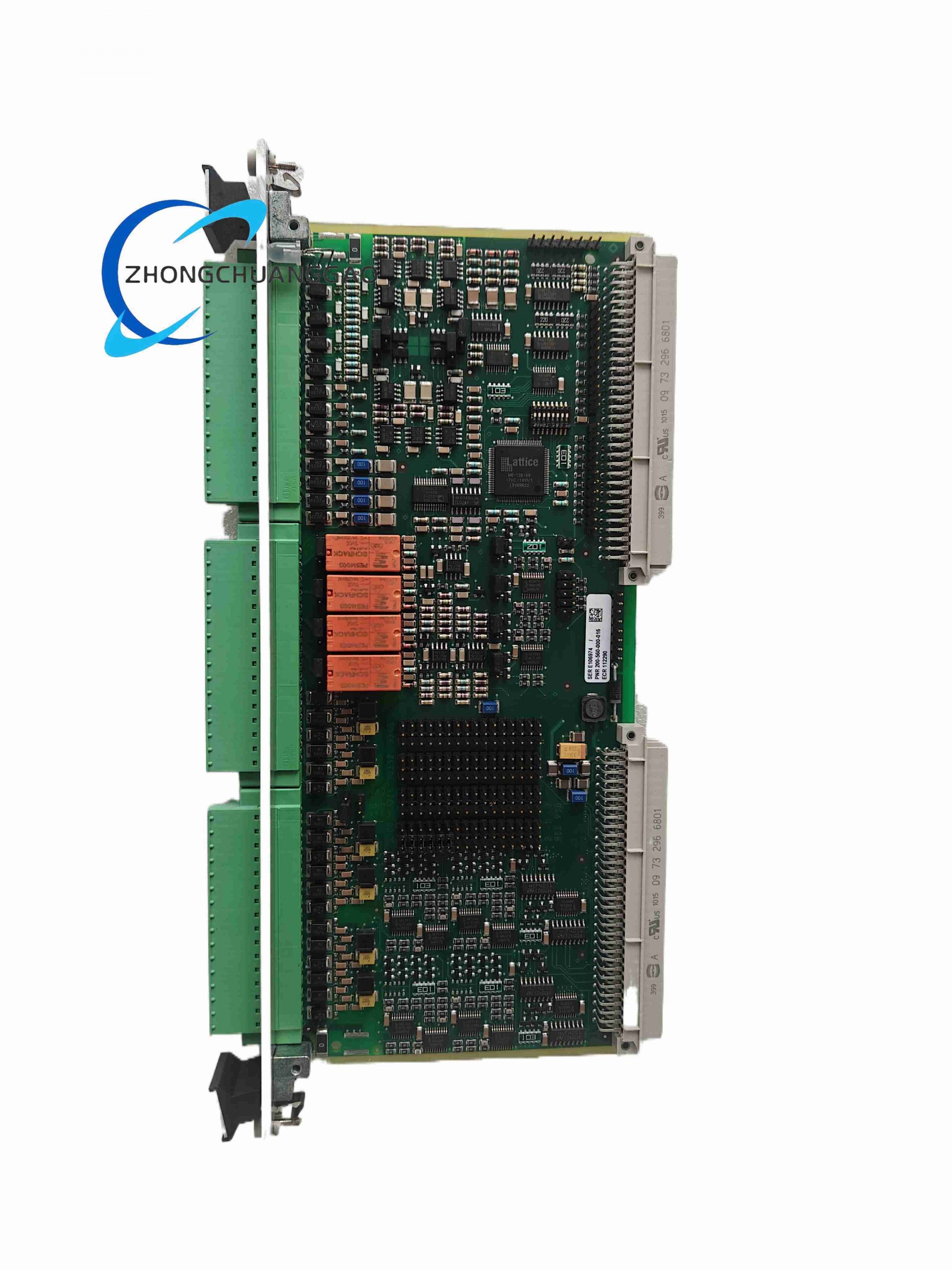
- Full Model Code: IOC4T, Order Part No. 200-560-000-016
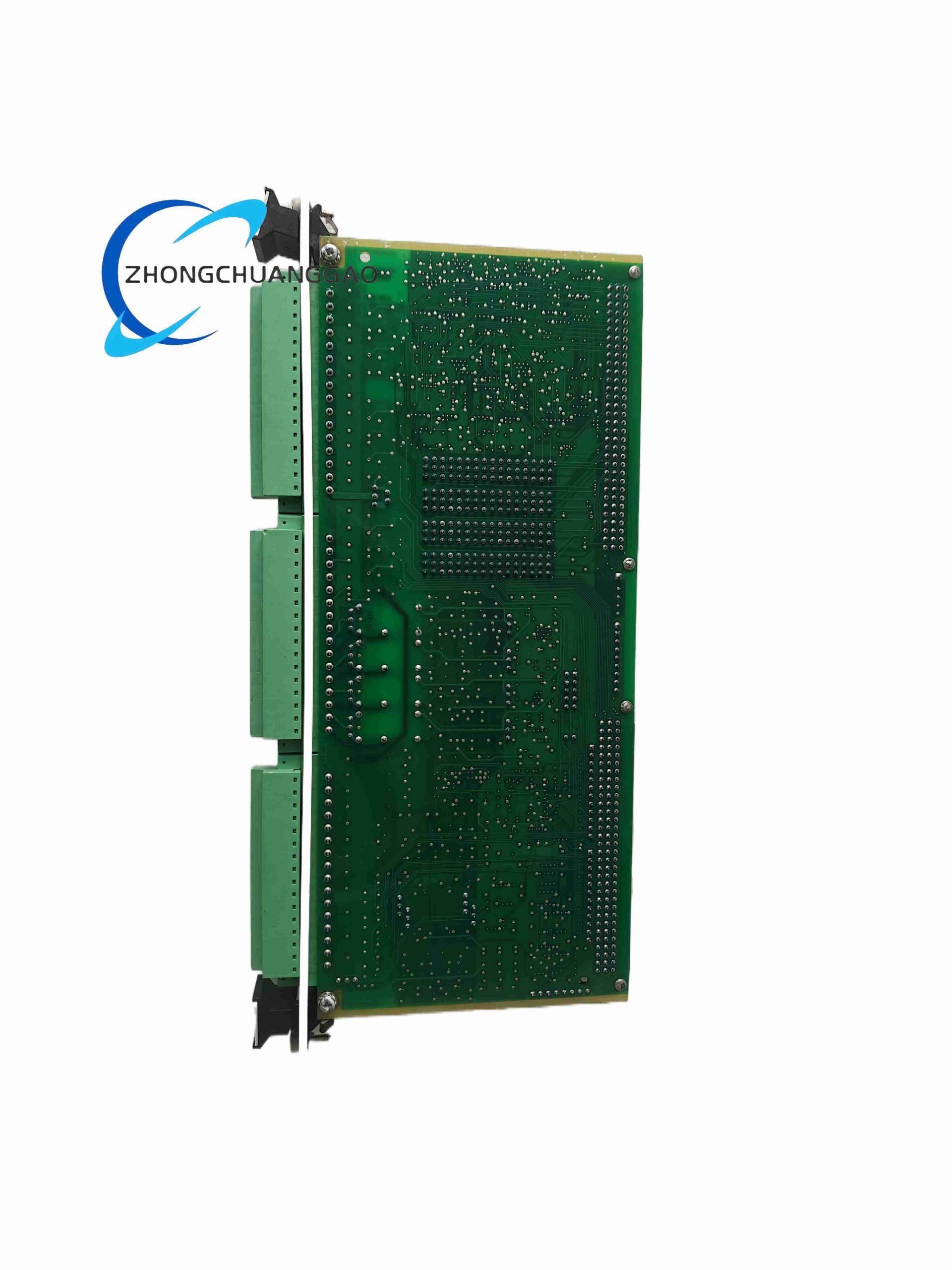
- Product Category: VM600 Rack Machinery Protection I/O Signal Interface Card
- Product Series: VM600 Turbomachinery Condition Monitoring System Series
Description
Product Overview
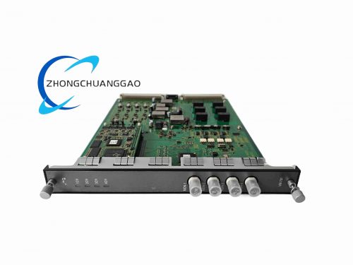
This card is a core signal input/output slave module matched with MPC4 processing card inside VM600 rack monitoring system, dedicated to acquiring vibration, velocity, displacement and rotational speed signals from proximity probes, accelerometers and speed sensors. It completes signal conditioning, analog conversion, relay alarm output and industrial bus data transmission, serving as the physical signal bridge between field rotating equipment sensors and system central processing unit for mechanical protection and predictive maintenance.
Technical Core Specifications
- Signal Input Channels
- 4 dynamic vibration analog input channels (compatible with eddy current, velocity, acceleration sensors)
- 2 speed/phase reference input channels (keyphasor signal collection)
- Signal Output Interfaces
- 4-channel DAC analog voltage output: 0–10 V DC calibrated vibration signal
- 4-channel V/I conversion current output: 4–20 mA configurable via on-board jumpers
- 4 built-in mechanical alarm relays (Form C SPDT contacts)
- Backplane & Communication
- VM600 proprietary rack backplane bus for MPC4 card data exchange
- External communication: Ethernet TCP/IP, Modbus TCP/RTU, PROFINET
- Power Supply
- Rack backplane DC 24 V supply, operating power consumption ≤12 W
- Per-channel sensor excitation power: software configurable −27.2 VDC / +27.2 VDC / +15 VDC / 6.16 mA, single channel output limit ≤25 mA
- Mechanical Dimensions & Weight
- Standard 2U Eurocard rack form factor: 88 mm (H) × 140 mm (W) × 180 mm (D)
- Net weight: 0.9 kg
- Environmental Rating
- Operating temperature: −20 °C ~ +70 °C
- Storage temperature: −40 °C ~ +85 °C
- Relative humidity: 5%–95% non-condensing
- Protection class: IP20 (indoor cabinet mounting only)
Functional Features
- On-board EMC surge and EMI filter for all input/output terminals, complying with IEC 61000-6-2 industrial EMC standards
- Independent channel AC/DC signal coupling mode configurable via external capacitive coupling adapter
- Real-time sensor wire breakage, short-circuit automatic diagnosis with hardware fault flag output
- Relay alarm logic programmable via VM600 configuration software; relays support hazard, alarm, sensor normal state signal output
- 32-bit digital alarm status transmitted to rack backplane for expansion relay card (RLC16/IRC4) linkage
- Built-in channel signal scaling, offset correction and temperature drift compensation circuit
- Continuous self-diagnosis for internal power circuit, DAC/ADC chip and backplane communication link
Working Principle
Field vibration/speed sensor raw signals enter the card’s front terminal block, pass through passive filter and surge protection circuit, then transmit to matched MPC4 processing card via rack backplane for FFT spectrum analysis and protection threshold judgment. Processed digital fault data returns to IOC4T card, converted to standard 0–10 V / 4–20 mA analog retransmission signals for DCS/PLC system access; meanwhile threshold trigger signals drive on-board relays to output hard-wired shutdown/interlock signals for turbomachinery safety protection.
Material & Structural Composition
- Main PCB substrate: FR4 high-temperature flame retardant industrial circuit board with gold-plated signal traces
- Enclosure: Cold rolled steel shielding frame with anti-electromagnetic interference coating
- Terminal connector: Screw-lock terminal strip with tin-plated copper conductive terminals
- Internal components: Industrial-grade DAC/ADC chips, optocoupler isolation chips, mechanical signal relays, multi-layer ceramic filter capacitors
Advantage Highlights
- SIL 2 functional safety certification per IEC 61508, applicable to safety critical turbomachinery protection loops
- Dual signal output mode (voltage + current) compatible with all mainstream industrial DCS and SCADA systems
- Independent channel sensor power supply configuration supports full series Vibro-Meter proximity and vibration sensors
- Wide operating temperature range adapts to offshore platform, refinery and power plant harsh cabinet environments
- Hot-swappable design without rack power cut for on-site module replacement
Applicable Industries
Thermal power generation, nuclear power auxiliary rotating equipment, oil & gas compressor stations, petrochemical refineries, offshore wind turbine gearbox monitoring, metallurgy large steam turbine, aviation gas turbine test bench
Installation Mandatory Requirements
- Install inside standard VM600 19-inch rack, fixed by front panel locking screws; must reserve 20 mm ventilation gap above and below card slot
- All field sensor wiring must use shielded twisted pair cable, cable shielding single-point grounded at cabinet ground bar
- AC coupling adapter must be locked with matching hex wrench on J3 terminal connector to prevent loose contact vibration
- Separate power wiring and signal wiring wiring trough to avoid cross electromagnetic interference
Operation & Maintenance Precautions
- Forbid plugging/unplugging module under live rack power supply except designated hot-swap slots
- Regular inspection of terminal screw torque (0.8–1.2 N·m) to prevent thermal drift from loose wiring
- Calibrate analog output channels every 12 months with standard signal generator
- Avoid mounting rack near high-power frequency converters or high-voltage contactors without additional shielding
Item 2: COMPRESSOR CONTROLS CORP IOC-555-D I7-550555-001 REV
Basic Product Identification
- Manufacturer: Compressor Controls Corporation (CCC, USA)
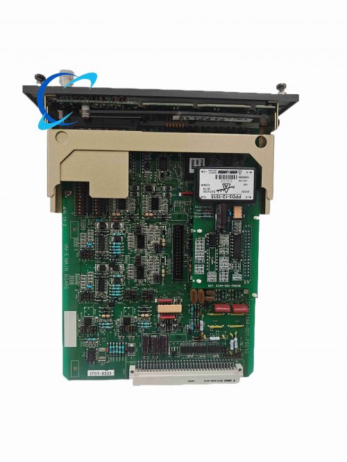
- Full Model Identifier: IOC-555-D, Hardware Part No. I7-550555-001
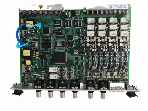
- Product Category: Simplex Compressor Dedicated I/O Processor Circuit Board
- Product Series: CCC TruboControl Compressor Anti-Surge Control System Series
Product Overview
This integrated input/output controller board is the core signal acquisition and execution unit of CCC industrial centrifugal/axial compressor anti-surge control system, responsible for collecting compressor field pressure, temperature, flow, valve position analog signals and emergency stop, safety door digital interlock signals, executing local PID anti-surge control algorithm, and communicating with upper host controller for real-time compressor operation closed-loop regulation.
Technical Core Specifications
- I/O Channel Configuration
- Analog Input (AI): 22 channels (0–10 V / 4–20 mA dual range, compatible with pressure transmitters, RTD temperature sensors)
- Analog Output (AO): 6 channels (4–20 mA for anti-surge valve, throttle actuator drive)
- Digital Input (DI): 16 channels (24 V DC dry contact safety interlock signals)
- Digital Output (DO): 8 channels (24 V DC relay contact for alarm light, shutdown solenoid valve)
- Communication Interfaces
- Isolated RS-485 bus, support Modbus RTU industrial protocol
- RS-232 local debugging serial port for on-site parameter configuration
- 10/100 Mbps Ethernet interface for host controller high-speed data exchange
- Power Supply Parameters
- Rated input power: 24 V DC / 5 A or 110/220 V AC dual universal power input
- Maximum operating power consumption: 18 W
- Isolation Performance
- All analog/digital channels reinforced isolation voltage: 2500 Vrms
- Mechanical Parameters
- Outer dimension: 127 mm (H) × 102 mm (W) × 229 mm (D)
- Net weight: 0.8 kg
- Mounting method: 35 mm standard DIN rail inside control cabinet
- Environmental Specifications
- Operating temperature: −20 °C ~ +60 °C
- Storage temperature: −40 °C ~ +85 °C
- Protection class: IP20
Functional Features
- On-board independent anti-surge control algorithm operation without relying on upper CPU, realizing fast local valve response within 10 ms when surge risk occurs
- Full-channel hardware overvoltage, overcurrent and reverse polarity protection circuit
- Built-in data historical log memory, storing 12 months of compressor surge event records with time stamp
- Real-time channel open-circuit, short-circuit fault diagnosis with front panel LED fault indicator light
- Configurable alarm threshold, surge curve lookup table via local serial port or Ethernet software
- Support dual redundant hot backup parallel operation for high-reliability compressor safety control loops
- Galvanic isolation between field signal side and internal control logic circuit to eliminate ground loop interference
Working Principle
Field compressor process analog and digital signals are collected by multi-channel front conditioning circuit, converted to digital data via high-precision ADC chip, then transmitted to on-board 32-bit microprocessor for real-time surge margin calculation according to pre-stored compressor performance curve. When calculated margin reaches warning/shutdown threshold, microprocessor drives analog output channel to adjust anti-surge valve opening, and triggers digital output interlock shutdown signal; meanwhile all operating data uploaded to upper CCC host controller via RS485/Ethernet bus for remote monitoring.
Material & Structural Composition
- PCB substrate: Thickened FR4 industrial high anti-interference circuit board with heavy copper power traces
- Enclosure: ABS flame retardant plastic integrated shell with metal shielding lining
- Terminal components: Spring-type quick lock copper alloy terminals with anti-corrosion nickel plating
- Core electronic parts: Industrial grade 32-bit ARM microprocessor, multi-channel isolated ADC/DAC chips, mechanical power relays
Advantage Highlights
- Professional algorithm optimized exclusively for centrifugal compressor anti-surge control, reducing compressor surge damage risk by 90%
- High channel density integrates analog and digital signals into single board, reducing cabinet wiring quantity and space occupation
- Reinforced channel isolation eliminates common industrial ground loop signal distortion
- Wide universal power input adapts to global plant AC/DC power supply standards
- Hot backup redundant architecture meets petrochemical and power plant SIL 2 safety control requirements
Applicable Industries
Oil & gas gathering stations, natural gas pipeline compression stations, petrochemical ethylene/propylene plants, refinery hydrogen compression systems, chemical fertilizer air separation plants, power plant boiler induced draft fan compressor auxiliary control
Installation Mandatory Requirements
- Mount vertically on 35 mm DIN rail, minimum 15 mm horizontal gap between adjacent modules for heat dissipation
- Analog signal cable must adopt shielded twisted pair, separate wiring trough from power cable
- Cabinet internal ground bus must connect module ground terminal with 4 mm² copper ground wire
- Ethernet communication wiring uses CAT6 industrial shielded network cable, maximum transmission distance ≤100 m
Operation & Maintenance Precautions
- All parameter modification must be completed under compressor standby state to avoid misoperation triggering surge shutdown
- Execute full channel signal calibration every 18 months with standard process signal calibrator
- Do not disassemble plastic shielding shell during operation to avoid electromagnetic interference causing control logic disorder
- Regularly clean front panel ventilation slits to prevent dust accumulation leading to overheating protection
Reviews
There are no reviews yet.