
Product Short Description
Product Brief Introduction
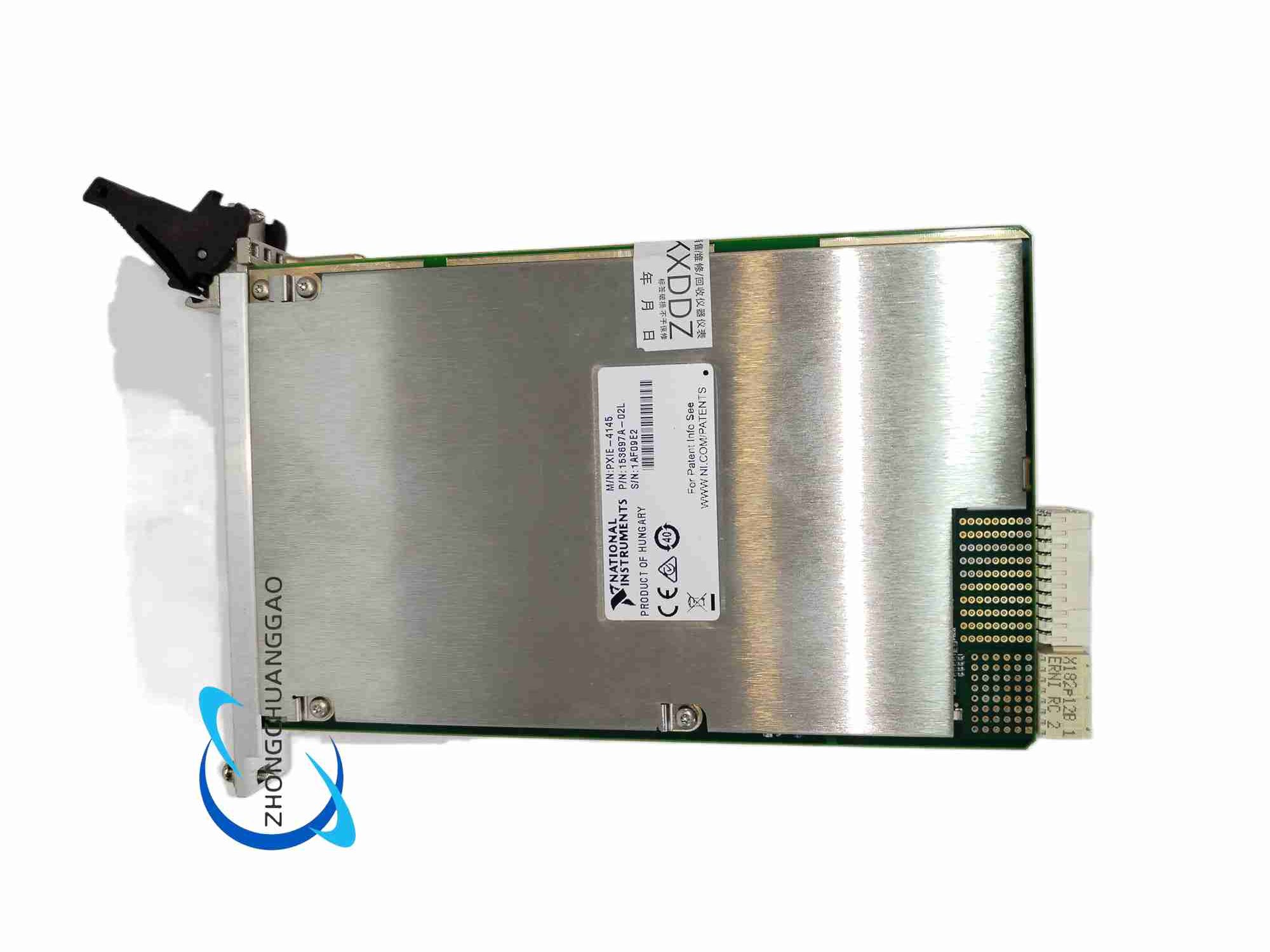
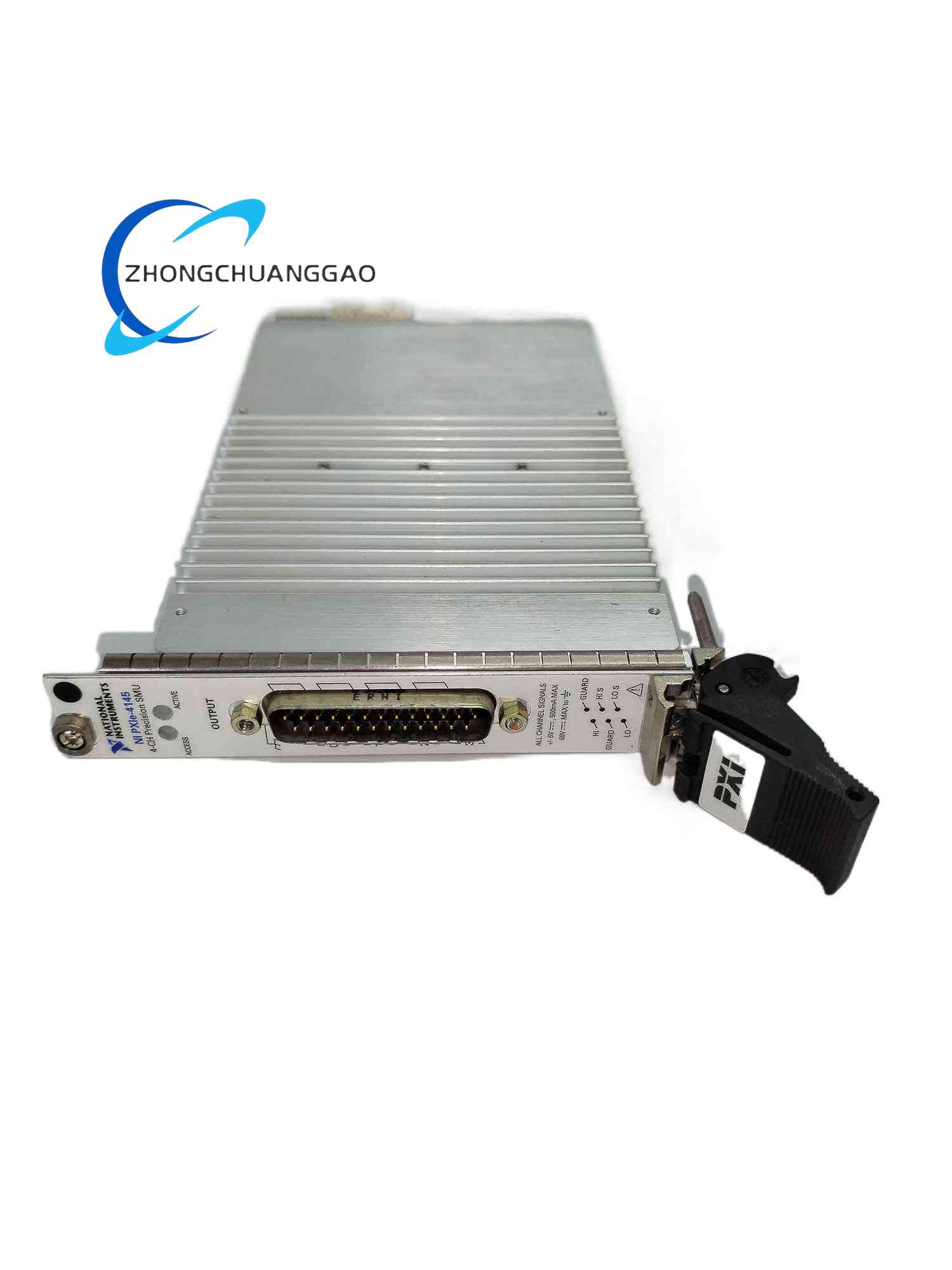
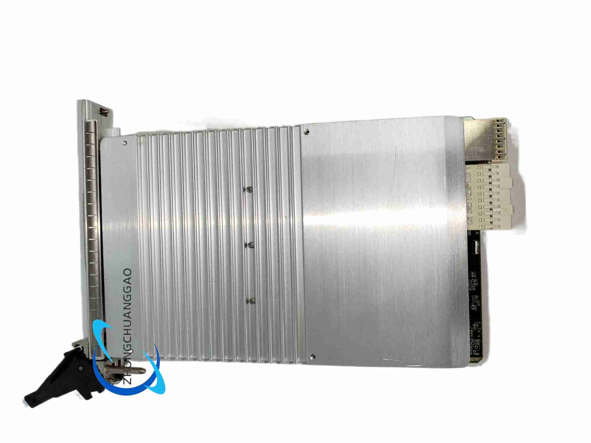
Description
Core Technical & Performance Specifications
- Channel Layout: Four fully independent, galvanically separated SMU measurement channels within single-width 3U PXI Express module
- Voltage Source & Measurement Full Scale: ±200 V DC per channel
- Current Source & Measurement Full Scale: ±500 mA DC per channel
- Single-Channel DC Power Rating: Maximum 60 W sourcing power, maximum 60 W sinking power, full four-quadrant bidirectional power operation
- Minimum Detectable Current Resolution: 1 nA low-level measurement sensitivity
- Sampling & Update Rate Metrics
- Maximum per-channel analog measurement sampling rate: 300 kS/s
- Maximum DC output setpoint update rate: 80 kS/s
- Transient Response Tuning: Three configurable speed profiles (Slow, Medium, Fast) for closed-loop regulation transient behavior matching DUT capacitive or inductive load characteristics
- Four-Wire Remote Sensing: Dedicated isolated sense terminals on front panel connector for high-voltage wiring loss compensation
- Onboard Data Storage: Independent per-channel FIFO measurement buffer for continuous streaming data capture without host PC bandwidth bottlenecks
- Physical & Environmental Specifications
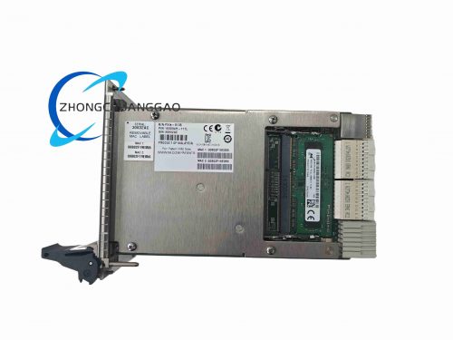
- Form Factor: Single-width 3U PXI Express module
- Operating Ambient Temperature Range: 0 °C to 55 °C
- Storage Temperature Range: -40 °C to 85 °C
- Relative Humidity Operating Rating: 10%–90% non-condensing
- Maximum Operating Altitude: 2000 m above sea level
Key Functional Features
- Four independent high-voltage high-power SMU channels packed into compact single-slot PXI Express hardware, drastically reducing chassis slot occupation for multi-device parallel power component testing
- Native four-quadrant bidirectional power handling allows sourcing power to DUTs and absorbing regenerative power from energy-generating components such as solar cells, supercapacitors and inductive power semiconductors
- Isolated four-wire remote sense circuit design specifically optimized for long high-voltage test cables; fully counteracts resistive voltage drop across thick high-voltage wiring, test fixture contact resistance and probe contact resistance
- Nanoscale low-current measurement capability with integrated low-noise shielding, supporting leakage current testing for high-voltage power transistors, ceramic capacitors and insulated gate power semiconductors
- Full compatibility with PXI Express backplane 10 MHz reference clock and star trigger bus, enabling nanosecond-level synchronized multi-channel and multi-module high-power device test sequencing
- Onboard industrial FPGA digital control logic offloads repetitive source-measure sequencing tasks from host PC CPU, eliminating communication latency and boosting automated test throughput for mass production screening stations
- Complete NI-DCPower instrument driver compatibility with LabVIEW, LabWindows/CVI, Python, C#, C++ and TestStand automated test sequencing software suites
- Multi-layer hardware fault protection architecture on each channel, including independent overvoltage, overcurrent, overpower, reverse polarity and thermal overload protection circuits to prevent DUT burnout and module internal power component failure during unsupervised long-duration testing
Working Principle
- High-Voltage Sourcing Regulation Path
Host control PC transmits target voltage and current setpoints over PXI Express high-speed serial backplane bus to onboard FPGA control logic. FPGA generates analog control signals driving dual closed-loop constant voltage / constant current high-voltage power amplifier circuits for each independent channel. The dual-loop regulation design enables automatic seamless switching between CV and CC operation modes without external relay switching hardware.
- Precision High-Voltage Measurement Path
DUT voltage and current signals are sampled simultaneously via two isolated high-voltage ADC converters per channel at maximum 300 kS/s sampling frequency. Isolated four-wire sense terminals connect directly to DUT contact points, feeding high-impedance buffered voltage signals to dedicated measurement ADC channels, fully bypassing resistive loss in high-voltage force wiring. Low-noise transimpedance amplifier preprocessing circuits amplify microamp and nanoamp low-current signals to measurable voltage ranges for high-resolution analog-to-digital conversion.
- Four-Quadrant Power Dissipation Operation
Each channel’s high-power bidirectional amplifier array supports bidirectional power flow. The module internal copper pour heat sink layers absorb regenerative power sinking from DUTs such as photovoltaic cells and inductive power semiconductors, converting excess electrical power into thermal energy dissipated through forced chassis cooling airflow.
- FPGA Timing Synchronization & Data Buffering
Onboard FPGA hardware independently executes closed-loop high-voltage regulation, multi-channel measurement sampling, hardware trigger signal generation and per-channel FIFO data buffer storage without relying on host PC CPU processing cycles. Front-panel BNC trigger I/O ports and PXI Express backplane trigger bus interface receive global chassis 10 MHz clock timing signals; FPGA logic aligns all channel source-measure sampling events to shared synchronous timing references for precise multi-module test synchronization.
- Multi-Stage Hardware Fault Protection Mechanism
Independent analog monitoring circuits continuously track each channel’s output voltage, output current and real-time power dissipation values. If measured values exceed user-programmable fault threshold limits, fault detection hardware instantly triggers a multi-stage channel isolation sequence: first disabling high-voltage power amplifier drive signals, then activating internal discharge circuits to safely bleed residual high-voltage charge stored within DUT capacitive loads, eliminating hazardous residual voltage risks before channel output isolation completes.
Structure & Material Composition
- Main Multi-Layer PCB: UL94 V-0 flame retardant FR4 high-voltage rated printed circuit board with separated analog, digital and high-voltage ground plane layers to suppress digital switching noise coupling into precision low-current analog measurement traces
- High-Voltage Precision Analog Components: High-withstand voltage JFET input operational amplifiers, high-stability high-voltage thin-film precision voltage divider resistors, low-leakage polypropylene high-voltage decoupling capacitors, matched transimpedance feedback resistor networks for nA-range low-current measurement
- High-Power Regulation Amplifier Hardware: High-withstand voltage bidirectional power MOSFET amplifier arrays, low-ESR high-voltage bulk power capacitors, high-temperature surface-mount power inductors, large-area copper PCB pour thermal dissipation layers for power amplifier heat extraction
- Digital Control Logic Hardware: Industrial-grade Xilinx FPGA chip, high-speed PXI Express serial physical layer transceiver ICs, low-jitter crystal oscillator timing reference circuits, non-volatile EEPROM memory storage for factory and user calibration coefficient datasets
- Front Panel Assembly: Die-cast aluminum alloy matte black powder-coated front panel with engraved channel number identification text, high-voltage rated multi-pin signal connector terminals for force output lines and four-wire remote sense lines, front-panel BNC coaxial trigger input/output connectors, stainless steel retention screw hardware for chassis slot mounting
- EMC & High-Voltage Isolation Shielding Components: Formed tin-plated steel internal compartment shielding cans to separate high-speed digital FPGA switching noise from low-noise precision analog measurement circuits; high-voltage insulation barrier dielectric layers integrated between high-voltage force traces and low-voltage measurement traces to eliminate cross-channel high-voltage leakage interference
Installation Mandatory Requirements
- Mechanical Module Installation Rules
Insert module only when target PXI Express chassis main AC power supply is fully disconnected from mains wall socket to avoid backplane bus short-circuit damage and electrostatic burnout of sensitive analog components. Slide module fully into selected chassis peripheral slot until front panel forms flush contact with chassis slot faceplate; evenly tighten left and right front-panel retention screws to ensure full electrical contact between module gold-plated edge connector and chassis backplane slot contacts. Install nylon plastic blank filler panels on all unused empty chassis slots to preserve uniform forced-air cooling internal airflow distribution and maintain chassis electromagnetic EMC shielding integrity.
- High-Voltage DUT Test Fixture Wiring Installation Rules
Use dedicated high-voltage rated shielded coaxial wiring bundles for each channel’s force output lines and four-wire remote sense measurement lines. Physically separate high-current high-voltage force wiring and high-impedance low-level sense wiring by minimum 5 cm clearance to eliminate capacitive and inductive EMI signal crosstalk interference between channels. Connect four-wire remote sense terminals directly to physical DUT contact points such as power semiconductor package pins or photovoltaic cell contact busbars; avoid connecting sense terminals to distant test fixture terminal block points to prevent residual wiring resistance measurement errors. Install external high-voltage rated series current-limiting resistors on all channel force output lines when characterizing fragile high-voltage semiconductor DUTs to provide secondary overcurrent fault protection backup alongside module onboard hardware fault protection circuits. All high-voltage test wiring must comply with local electrical safety standards for high-voltage measurement equipment.
- PXI Express Chassis Synchronization Installation Rules
Ensure chassis backplane 10 MHz low-jitter reference clock and star trigger bus hardware are fully enabled and functional. Route inter-module synchronization trigger signals via chassis internal backplane trigger bus rather than external front-panel BNC trigger cables to minimize trigger signal propagation delay jitter and eliminate external EMI noise interference on timing reference signals.
- Software Driver Installation Rules
Install complete NI-DCPower instrument driver software suite matching the host operating system version prior to chassis power-up and module hardware detection. Launch NI MAX measurement automation configuration software after chassis power-on to execute automated module hardware discovery, run full onboard hardware self-test diagnostic routines, verify multi-channel high-voltage analog measurement calibration integrity, and allocate system hardware memory and interrupt resources to the module. Configure channel-specific fault protection threshold limits (overvoltage, overcurrent, overpower), constant voltage/current source mode operating parameters, and four-wire remote sense measurement enable/disable settings within NI MAX prior to deploying custom automated power component characterization test application code.
Strict Usage Precautions
- High-Voltage Electrical Safety Precautions
All test operators must wear certified insulated high-voltage safety gloves during wiring modification, DUT replacement and front-panel signal cable connection operations. Never touch exposed metal high-voltage wiring terminals or DUT contact probes when the module channel output is active and sourcing high voltage. Ensure all high-voltage test cables feature fully insulated outer jackets and intact strain relief connectors; cracked, split or damaged high-voltage cables must be replaced immediately to prevent electric shock hazards. Do not operate the module in environments with conductive metal dust, water splashes or high condensation humidity, as conductive contaminants create hazardous high-voltage leakage paths between signal terminals and chassis ground.
- Thermal Power Dissipation Precautions
Maintain chassis cooling fan operation at HIGH fixed speed mode during continuous full-load four-channel simultaneous maximum 60 W power sourcing/sinking operation. Sustained high power dissipation across all four channels generates substantial internal thermal load which requires maximum forced-air cooling airflow volume to prevent module internal power amplifier component thermal throttling and over-temperature automatic shutdown fault events. Avoid stacking multiple high-power SMU modules in adjacent chassis peripheral slots without maximum cooling fan speed enabled; concentrated localized heat buildup between adjacent power-heavy modules creates uneven thermal distribution and accelerates internal component aging and drift of precision analog measurement calibration coefficients.
- Precision Low-Current Measurement Noise Precautions
Operate module exclusively inside properly EMC-shielded PXI Express chassis with all empty slots fitted with plastic filler panels; unshielded open chassis operation allows external industrial electromagnetic interference noise to corrupt ultra-low-level nA-range current measurement data, introducing severe measurement inaccuracies. Route all DUT test fixture shielded high-voltage signal wiring away from high-voltage AC mains power cables, industrial motor drive wiring, relay control wiring, and switching power supply wiring to eliminate inductive and capacitive EMI noise coupling into precision analog measurement signal lines.
- ESD Electrostatic Discharge Precautions
Wear certified ESD grounding wrist strap with ground lead securely connected to chassis rear protective earth screw before handling module front high-voltage signal wiring, DUT probes, or unpopulated power semiconductor DUT boards. All spare SMU modules must be sealed within factory anti-static shielding bags during storage to prevent static charge accumulation damaging sensitive low-leakage analog amplifiers.
- Calibration & Long-Term Measurement Accuracy Precautions
Execute full module self-calibration procedure inside NI MAX at stable 25°C ambient temperature before high-precision low-current high-voltage characterization tests. Avoid frequent rapid temperature fluctuation of the chassis environment; thermal cycling shifts high-voltage thin-film precision resistor values and introduces permanent measurement offset drift if operating temperature varies more than ±5°C during continuous testing. Schedule annual factory full calibration service to maintain module high-voltage measurement accuracy specification compliance over long-term industrial production operation.
Target Application Scenarios for NI PXIe-4145
- Power semiconductor device characterization including IGBTs, MOSFETs, silicon carbide (SiC) and gallium nitride (GaN) wide-bandgap power transistors
- Photovoltaic solar panel sub-cell, solar module and miniature energy harvester power output testing
- High-voltage ceramic and film capacitor leakage current, charge-discharge cycle lifetime validation
- Industrial power supply component, relay contact and high-voltage switching device end-of-line automated production screening
- Research laboratory testing of supercapacitors, rechargeable high-voltage battery cells and inductive power conversion circuit components
Reviews
There are no reviews yet.