
Product Short Description
Product Brief Introduction
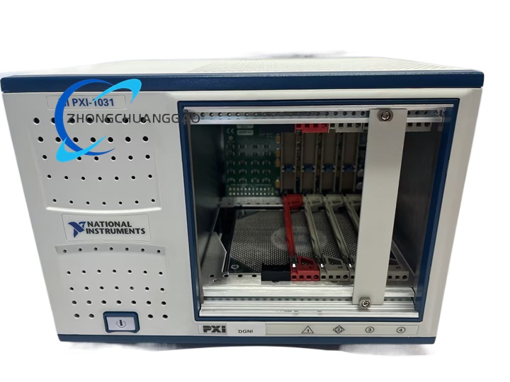
5-slot PXI Rev2.2 compliant bench/rack-mount chassis with integrated onboard MXI-Express remote control interface, purpose-built for distributed remote test measurement systems where the PXI hardware rack must be physically separated from the host control PC. Equipped with universal AC power supply, temperature-controlled variable cooling fan, complete PXI synchronization bus architecture, and dedicated star trigger slot for multi-module synchronized high-speed measurement operations
Description
Core Technical & Performance Specifications
- Slot Layout Configuration: Total 5 slots, 1 dedicated MXI-Express integrated remote controller slot + 4 standard PXI peripheral I/O slots; dedicated star trigger synchronization slot integrated within backplane bus architecture
- MXI-Express Remote Control Interface Specifications
- Interconnect Standard: MXI-Express x1 serial remote communication bus
- Maximum Remote Link Bandwidth: 2 GB/s bidirectional data throughput between chassis and host PC MXI-Express host card
- Maximum Physical Remote Cable Length: Up to 10 meters with factory-supplied shielded MXI-Express copper cable assemblies
- Backplane Timing & Synchronization Specifications
- Onboard Low-Jitter 10 MHz shared system reference clock distributed to all 5 slots
- Full PXI star trigger bus, local inter-slot communication bus, multi-layer analog/digital trigger routing bus
- Electrical Power Supply Specifications
- AC Input Voltage Universal Range: 100–240 VAC nominal, operating tolerance 90–264 VAC
- Input Operating Frequency Band: 47–63 Hz, nominal 50/60 Hz mains frequency
- Rated Input Current Draw: 2 A to 4 A
- Full-Load Power Supply Efficiency Rating: ≥70% under maximum rated module load conditions
- Stabilized DC Backplane Power Rails: +3.3 V, +5 V, ±12 V; line regulation ≤±0.2% (+3.3 V rail), ≤±0.1% (+5 V / ±12 V rails)
- Integrated overvoltage, overcurrent, short-circuit protection circuits for all DC power output rails
- Cooling & Acoustic Noise Specifications
- Dual-mode AUTO/HIGH brushless DC cooling fan control system
- Minimum acoustic noise emission at AUTO low-speed mode: 35 dBA (ISO 7779 standard operator-position sound pressure measurement)
- Onboard intake air temperature sensor for automatic fan speed dynamic adjustment logic
- Physical & Environmental Specifications
- External Dimensions: Width 257.1 mm, Height 177 mm, Depth 340 mm
- Total Unit Weight: 5 kg
- Operating Ambient Temperature Range: 0 °C to 55 °C
- Storage Temperature Range: -40 °C to 85 °C
- Relative Humidity Operating Rating: 10%–90% non-condensing
- Maximum Operating Altitude: 2000 m above sea level
Key Functional Features
- Integrated onboard MXI-Express remote controller eliminating requirement for separate dedicated PXI remote control module; enables transparent remote communication between separated chassis and host desktop/laptop control PC
- Five-slot expanded peripheral channel capacity compared to the 4-slot PXI-1031 chassis, supporting additional multi-channel I/O, digitizer, and SMU measurement modules within a single compact chassis unit
- Complete PXI Rev2.2 synchronization infrastructure: distributed 10 MHz low-jitter reference clock, dedicated star trigger slot, inter-slot local bus, multi-path trigger routing bus for multi-module time-aligned synchronized test and measurement operations
- Dual-speed temperature-controlled cooling fan with AUTO automatic speed adjustment logic to minimize acoustic noise emissions in quiet laboratory/office operating environments; HIGH fixed full-speed mode available for continuous high-power full module load operation
- Front-panel momentary standby power switch for convenient system power cycling without full AC mains cable disconnection
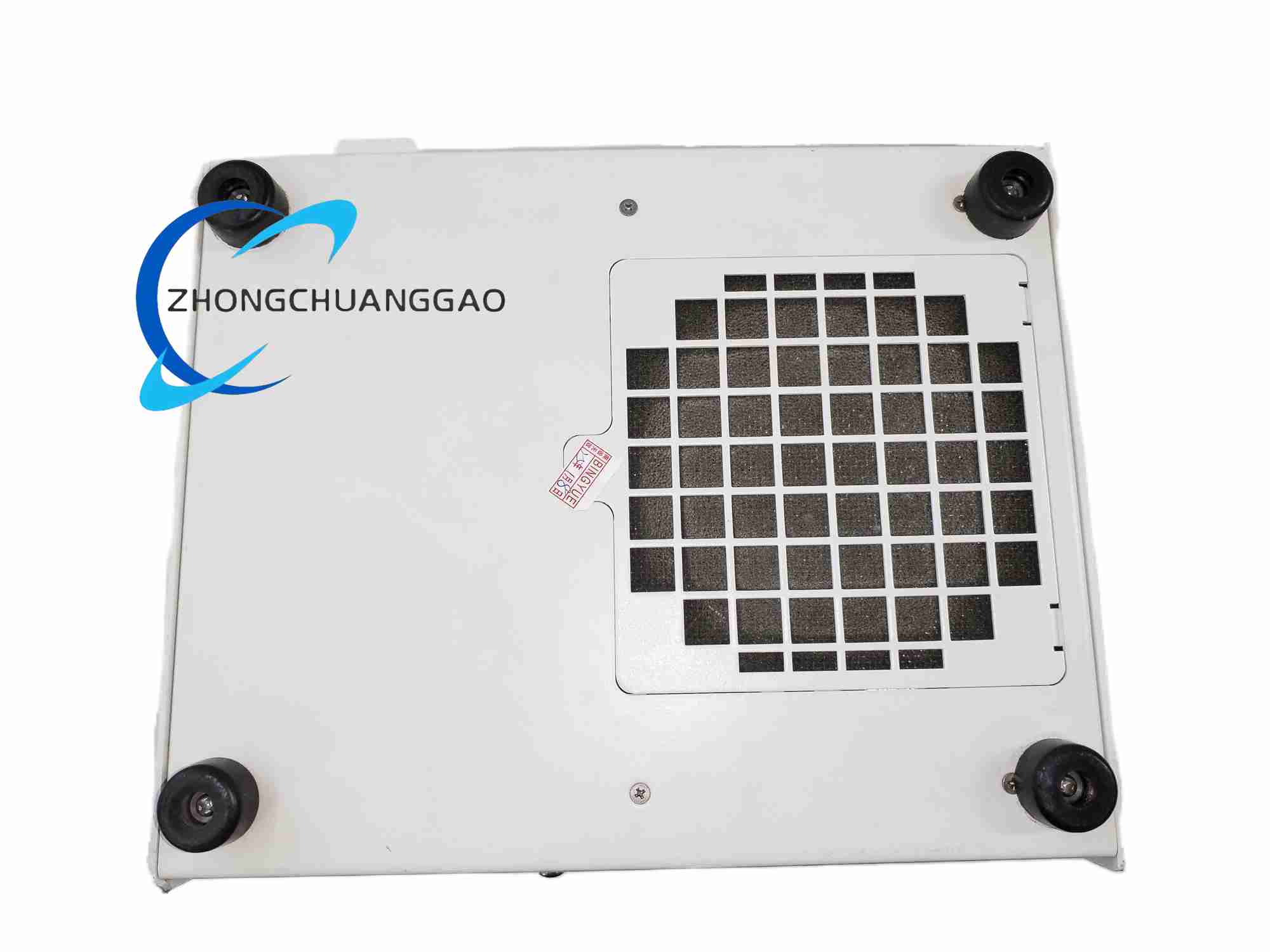
- Full mechanical accessory compatibility: optional portable carrying handle kit, standard 19-inch industrial rack-mount bracket kit, anti-slip bottom rubber feet for desktop bench placement
- Comprehensive hardware resource configuration and diagnostic support via NI MAX measurement automation software; automatic generation of pxisys.ini system definition file for remote chassis hardware identification, resource allocation, and cross-link communication configuration
- Universal AC input power supply with automatic mains voltage/frequency range detection, eliminating manual input voltage selection switches for global worldwide deployment compatibility
Working Principle
- AC mains power conversion stage: External universal AC input power feeds integrated internal switching power supply unit, which converts wide-range AC input voltage to stabilized multi-channel DC power rails (+3.3 V, +5 V, ±12 V) to supply power to the PXI backplane PCB and all installed peripheral modules
- Backplane signal distribution stage: The multi-layer backplane printed circuit board distributes stabilized DC power supply rails, PCI Express data communication bus lines, 10 MHz synchronous reference clock signals, and multi-layer trigger bus pathways evenly to all five installed hardware module slots
- MXI-Express remote communication working principle
- The dedicated integrated MXI-Express controller slot onboard circuit hardware acts as transparent serial communication bridge between the PXI backplane internal PCI bus and external MXI-Express remote copper cable
- Host control PC fitted with complementary MXI-Express host adapter card transmits measurement command signals and receives acquired test data bidirectionally over the shielded MXI-Express remote cable link
- All PXI hardware modules installed within the remote chassis appear as locally connected native PCI hardware devices to the host operating system; no custom proprietary software translation layers required for remote test application code execution
- Thermal fan control working principle: High-precision onboard thermistor temperature sensor continuously samples chassis intake air temperature values, feeding temperature measurement data to dedicated fan speed control logic circuit. When internal chassis temperature rises above predefined factory calibration threshold, control logic automatically increases brushless DC fan rotation speed to boost forced-air cooling airflow volume
- Synchronization clock distribution working principle: High-stability low-jitter 10 MHz crystal oscillator circuit generates universal synchronous timing reference signal, which is buffered and distributed to every hardware module slot via dedicated matched-impedance clock signal traces on the backplane PCB. All installed measurement modules lock their internal sampling clock timing to this shared chassis reference signal to achieve precise nanosecond-scale time alignment across multi-channel, multi-module test measurement systems
Structure & Material Composition
- Chassis Outer Enclosure Frame: Formed sheet aluminum structural frame combined with cold-rolled steel side panel assemblies
- Exterior Surface Finishing Treatment: Aluminum structural components coated with clear chromate conversion anti-corrosion coating; steel side panels processed with electrodeposited nickel plating base layer + matte black polyester urethane powder topcoat for scratch and chemical resistance
- PXI Backplane Bare Circuit Board: UL94 V-0 flame retardant multi-layer FR4 printed circuit board with gold-plated slot connector contact pads and matched-impedance high-speed signal traces
- Backplane Slot Connectors: IEC 917 & IEC 1076-4-101 standard compliant gold-plated signal connectors with UL94 V-0 rated glass-filled nylon plastic housing
- Internal Cooling Fan Assembly: High-efficiency brushless DC motor, lightweight aluminum fan impeller blades, flame retardant plastic fan housing structure
- Mechanical Support & Accessory Components: Extruded aluminum internal support brackets, nylon plastic blank filler panels for unused empty chassis slots, die-cast aluminum front panel retention screw hardware
Installation Mandatory Requirements
- Mechanical Installation Rules
- Desktop bench deployment: Install all four factory-provided rubber anti-slip feet to the chassis bottom surface to create mandatory bottom intake airflow clearance and prevent chassis sliding during operation
- 19-inch industrial equipment rack mounting: Deploy official NI matching rack-mount accessory bracket kit; install nylon plastic filler panels on every unused empty chassis slot to preserve uniform forced-air cooling internal airflow distribution
- Portable mobile field measurement deployment: Mount optional factory carrying handle kit to chassis side panel mounting points; restrict chassis operational tilt angle to maximum 15 degrees to avoid internal liquid capacitor fluid leakage damage
- Electrical Installation Rules
- Establish reliable protective earth ground connection by fastening copper ground wire to the rear-panel dedicated chassis ground screw terminal to eliminate ESD electrostatic discharge risk and reduce electromagnetic EMI signal interference
- Only utilize factory-matched regional AC mains power cables compatible with local wall socket standards (NEMA 5-15 North America, SEV European, AS C112 Australian regional variants)
- Insert, remove, or reconfigure any PXI peripheral hardware modules exclusively when chassis main AC power cable is fully disconnected from mains wall socket to prevent backplane PCB short-circuit damage and module component burnout
- MXI-Express Remote Link Installation Rules
- Connect factory-supplied shielded MXI-Express x1 copper remote cable between chassis rear-panel MXI-Express port and host PC installed MXI-Express host adapter card port; avoid cable routing alongside high-voltage industrial power cables to minimize signal crosstalk interference
- Maintain maximum cable length restriction of 10 meters for standard copper MXI-Express cable assemblies; longer remote separation distances require fiber-optic MXI-Express extender hardware accessories
- Software Configuration Installation Rules
- Install complete NI DAQmx driver suite and NI MAX measurement automation configuration software on the remote host control PC prior to powering on the PXI-1033 remote chassis
- After chassis power-up, launch NI MAX software to execute automated remote chassis hardware discovery, run full hardware self-test diagnostic routines, verify MXI-Express remote link communication integrity, and allocate system hardware memory and interrupt resources to all installed chassis peripheral modules
Strict Usage Precautions
- Thermal Cooling Precautions
- Never physically block front-panel chassis intake air vents or rear-panel hot exhaust air vents; maintain minimum 100 mm unobstructed clearance at chassis rear exhaust side for hot air dissipation
- Mandatorily install nylon filler panels on all unused empty chassis slots; missing filler panels create uneven internal airflow patterns, causing localized module overheating and accelerated hardware component aging
- When operating multiple high-power power supply, digitizer, or SMU measurement modules simultaneously within the chassis, manually switch cooling fan to fixed HIGH speed mode to prevent thermal throttling and module temperature limit overshoot
- Electrical Safety Precautions
- Disconnect main AC mains power cable before performing any module insertion, removal, chassis internal maintenance, or field wiring reconfiguration procedures
- Do not operate chassis utilizing damaged, frayed, cracked, or improperly terminated AC power cables; defective power cables present severe electric shock and fire hazard risks
- Restrict chassis operation to indoor dry environments only; avoid deployment in environments with conductive metal dust, liquid water splashes, condensation, or ambient relative humidity exceeding 90% non-condensing rating
- Mechanical Handling & Storage Precautions
- Handle chassis unit with extreme care; avoid dropping, heavy physical impact, or severe mechanical vibration exposure during transportation or field operation, as impact force can crack the delicate multi-layer backplane PCB or permanently deform gold-plated slot connector contact pins
- For long-term inactive chassis storage: Remove all installed peripheral measurement modules, store chassis in temperature-controlled dry storage space with ambient humidity maintained between 20%–60%, wrap chassis unit in moisture-barrier plastic protective film to prevent metal component corrosion
- Clean chassis exterior surface only utilizing dry soft lint-free microfiber cloth; never spray liquid cleaning solvents directly onto chassis enclosure or blow compressed air into internal chassis ventilation openings
- ESD Electrostatic Discharge Precautions
- Wear certified ESD grounding wrist strap with ground lead connected securely to chassis rear-panel protective earth ground screw terminal before handling installed peripheral modules or performing chassis internal maintenance procedures
- Store spare uninstalled measurement modules inside original factory antistatic shielding bags when not installed within a powered chassis unit
Target Application Scenarios
- Distributed remote industrial automated test systems where test hardware rack must be physically separated from host control PC (electromagnetic noise isolation, hazardous high-voltage test cell physical separation requirements)
- Automotive powertrain, battery pack, and vehicle electronic component end-of-line production test stations requiring remote chassis deployment within sealed noise-isolated test enclosures
- Aerospace and defense avionics component environmental chamber test systems (thermal/vibration environmental chambers require test hardware placement inside sealed chamber with remote host PC control outside chamber)
- Semiconductor wafer probe station characterization test systems where measurement chassis must be mounted adjacent to vacuum probe station hardware with host control PC located outside cleanroom production zones
- Large-scale multi-channel sensor data acquisition field measurement systems for civil engineering structural load testing, wind tunnel aerodynamic characterization, and environmental monitoring deployments
- Research laboratory multi-module synchronized signal generation and high-speed digitization test benches requiring remote separation of measurement hardware from sensitive low-noise host control computing equipment
Reviews
There are no reviews yet.