
Product Short Description
Product Overview
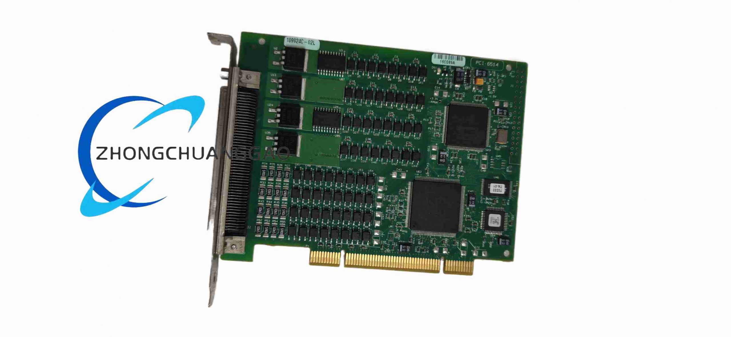
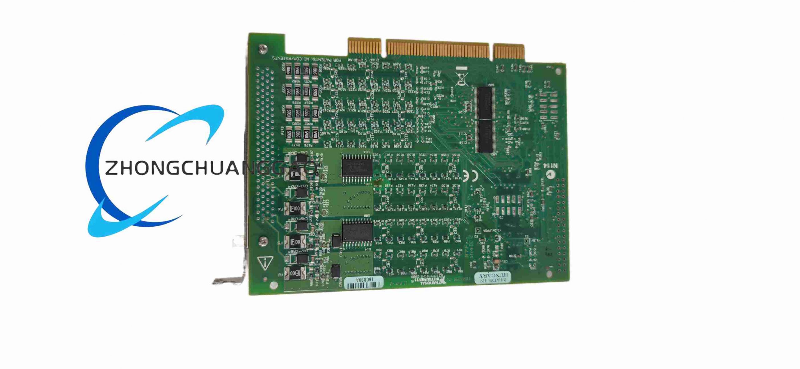
The PCI-6514 is a dedicated industrial isolated digital input and output PCI bus expansion board launched by National Instruments, focusing on pure digital signal acquisition and control without analog measurement channels. This device adopts high voltage optical isolation design for all digital ports, which is specially applied to industrial automation production lines, PLC auxiliary expansion, relay matrix control, multi-point equipment status detection scenarios, effectively resisting industrial field high voltage surge, ground loop interference and electromagnetic noise.
Description
Isolated Digital Input Channels
- Input Channel Quantity: 32 isolated digital sinking input channels
- Input Logic Standard: 24 V industrial NPN sinking input standard
- Channel-to-ground Isolation Withstand Voltage: 250 Vrms continuous isolation
- Input Threshold Voltage: Logic high ≥10 V DC, logic low ≤3 V DC
- Built-in per-channel input overvoltage protection circuit
Isolated Digital Output Channels
- Output Channel Quantity: 32 isolated digital sourcing output channels
- Output Logic Standard: 24 V industrial PNP sourcing output standard
- Channel-to-ground Isolation Withstand Voltage: 250 Vrms continuous isolation
- Single Channel Maximum Output Current: 500 mA per output channel
- Built-in output short-circuit automatic current limiting protection circuit
Timing & Synchronization System
- Onboard 32-bit event counter for digital signal edge counting
- Internal Reference Clock Accuracy: ±50 ppm under 25 ℃ standard working temperature
- Multi-board Synchronization: RTSI bus hardware interface supports synchronous digital signal triggering and timing synchronization among multiple PCI-6514 digital I/O boards
Bus Interface Standard
- Bus Type: Standard 32-bit 33 MHz PCI bus
- Maximum Digital Data Transmission Rate: 1 MB/s aggregate input and output data rate
8.4 Functional Features
- 32-channel isolated digital sinking input + 32-channel isolated digital sourcing output integrated design, realizing simultaneous multi-point equipment status detection and multi-group relay control on one single PCI board
- Full-channel 250 Vrms optical isolation, completely cutting off ground loop interference between industrial field 24 V equipment and host computer control system
- Industrial standard 24 V NPN input and PNP output logic, directly matching industrial proximity switches, photoelectric sensors, 24 V DC relays and solenoid valves without additional signal conversion modules
- Each digital output channel supports 500 mA large current drive, capable of directly driving small-power 24 V DC actuators without intermediate relay expansion
- Built-in per-channel overvoltage protection for digital input channels and automatic current limiting short-circuit protection for output channels, avoiding circuit damage caused by field wiring errors
- Onboard 32-bit event counter module for counting digital input edge signals, realizing production line workpiece counting, equipment pulse signal statistical functions
- Complete NI-DAQmx driver compatibility, supporting LabVIEW, Python, MATLAB, C#, C++ mainstream industrial automation development environments
- RTSI bus multi-board synchronous triggering function, realizing large-scale multi-card combined digital I/O expansion for ultra-multi-channel industrial control systems
8.5 Application Scenarios
- Automotive assembly line multi-station photoelectric sensor signal collection and conveyor belt relay control
- Factory PLC digital I/O channel capacity expansion for multi-group solenoid valve matrix control
- Packaging machinery production line workpiece counting, equipment limit switch status real-time monitoring
- Warehouse automated sorting equipment photoelectric proximity switch multi-channel signal acquisition
- Chemical factory explosion-proof area low voltage digital sensor isolated signal collection and valve on-off control
- Railway signal auxiliary detection equipment multi-point digital status signal collection
- Laboratory automated test fixture multi-group relay switching control
8.6 Performance Parameters (Typical under 25℃)
- Continuous Operating Temperature Range: 0 ℃ ~ 55 ℃
- Storage Temperature Range: -40 ℃ ~ 85 ℃
- Peak Total Power Consumption: 15.8 W
- Maximum Continuous Uninterrupted Working Time: 1000 hours without isolation performance attenuation
- Maximum Single Channel Continuous Output Load: 500 mA 24 V DC resistive load
8.7 Material & Construction Composition
- Main Circuit Substrate: Multi-layer FR-4 high insulation fire-resistant printed circuit board, independent digital input isolation area, digital output isolation area and PCI bus communication ground plane, wide high-insulation isolation strips between isolation regions
- Core Processing Chips: High withstand voltage linear optocoupler isolation chips for all digital input and output channels, Xilinx dedicated digital I/O control FPGA, 32-bit event counter logic integrated circuit
- Front Panel Connector: Two groups of multi-pin metal shielded D-SUB connectors with built-in EMI rubber sealing gaskets, one connector for 32 input channels and one connector for 32 output channels
- Mechanical Fixing Components: Cold rolled steel full-height PCI mounting bracket with zinc anti-corrosion electroplating surface treatment
- Passive Electronic Components: High insulation low temperature drift metal film precision current limiting resistors, high withstand voltage ceramic bypass capacitors, ferrite magnetic bead EMI suppression components for all input and output signal traces
8.8 Structural Characteristics
- Form Factor: Standard full-length 32-bit 33 MHz PCI bus expansion board
- Physical Overall Dimensions: Width 10.6 cm, Length 17.5 cm
- PCB High-insulation Partition Design: Digital input optocoupler isolation circuit area and digital output optocoupler isolation circuit area separated by wide high-insulation PCB isolation strips to guarantee 250 Vrms continuous isolation withstand voltage performance
- Thermal Dissipation Layout: High-density copper thermal vias laid under FPGA and optocoupler array high-power components for passive convection heat dissipation without additional cooling fans
- EMI Shielding Layout: Closed copper ground shielding layer around PCI bus communication digital traces; each group of 8 digital channels equipped with independent small shielding ring to prevent cross-channel digital signal crosstalk
8.9 Working Principle
- Isolated Digital Input Signal Acquisition Stage: Industrial field 24 V NPN sinking digital signal enters per-channel current limiting protection circuit first, then transmits to high voltage optocoupler isolation chip; optocoupler completely isolates industrial field 24 V ground potential and host computer PCI board internal ground; optocoupler converts external 24 V digital signal into internal 5 V TTL digital signal and transmits to onboard FPGA control chip
- FPGA Digital I/O Control & Counter Logic: Onboard dedicated FPGA collects all isolated digital input signals in real time, buffers input data to onboard FIFO memory and transmits data to host computer via PCI bus; FPGA receives digital output control instructions sent by host computer, distributes target output logic level to each isolated output channel; onboard 32-bit counter module captures rising and falling edges of digital input signals to complete pulse counting statistical work
- Isolated Digital Output Signal Drive Stage: FPGA outputs internal 5 V TTL digital control signal to high voltage optocoupler isolation chip; optocoupler isolates host computer internal control circuit and industrial field 24 V output load circuit; optocoupler drives external 24 V PNP sourcing output circuit, outputs 24 V DC current to drive external relays, solenoid valves and other actuators; per-channel automatic current limiting circuit monitors output current in real time, cuts off output current automatically when short-circuit fault occurs to protect internal circuit components
- RTSI Multi-board Synchronization Logic: RTSI bus transmits unified synchronous trigger signals between multiple PCI-6514 digital I/O boards, realizing simultaneous digital input signal sampling and synchronous digital output action execution of all connected boards, meeting ultra-multi-channel large-scale industrial control system expansion requirements
8.10 Installation Requirements
- Host PC Expansion Slot: Unoccupied full-length 32-bit PCI motherboard expansion slot; computer chassis must be equipped with forced air cooling fan to maintain internal temperature within rated operating range
- Pre-operation Warm-up Requirement: After powering on the host computer, maintain continuous power supply for at least 5 minutes before executing digital signal collection and control tasks to stabilize optocoupler isolation signal transmission performance
- Mechanical Installation Steps: Remove the metal blank baffle of the chassis expansion slot; align the gold-plated edge connector of the PCI board with the motherboard PCI slot; fully insert the board until the connector is completely seated; tighten the fixing screw of the steel mounting bracket to the chassis frame to eliminate PCB mechanical vibration
- Isolated Digital Signal Wiring Specifications: All industrial field 24 V digital input and output wiring adopts shielded twisted pair cables; connect the outer shielding layer of the cable to the metal shell of the D-SUB connector to form low-impedance EMI ground reference; strictly separate field 24 V digital signal cables and host computer internal power cables to avoid high voltage breakdown of PCB isolation barriers
- Software Driver Installation Process: Download and install the latest NI-DAQmx driver software matching the host operating system; launch NI MAX hardware configuration tool, the software automatically identifies PCI-6514 isolated digital I/O hardware equipment; configure digital input/output logic mode and channel protection parameters in NI MAX software according to on-site industrial equipment wiring standard
8.11 Operation Precautions
- Isolation Voltage Limit Restriction: Do not continuously input channel-to-ground voltage exceeding 250 Vrms; excessive voltage will break down internal optocoupler isolation barriers and permanently damage the entire digital I/O board
- ESD Static Discharge Protection Rule: Wear a grounded anti-static wristband before touching PCB boards, connectors and internal circuit components; electrostatic discharge will permanently damage sensitive optocoupler and FPGA chips
- Chassis Cooling Mandatory Requirement: Do not run PCI-6514 with the side panel of the host computer chassis removed; insufficient air convection will cause serious thermal drift of optocoupler signal transmission, unstable digital input reading and output drive capacity attenuation
- Cable Separation Specification: Strictly separate isolated field 24 V digital signal cables and high-power industrial motor, inverter wiring to prevent high voltage surge from breaking down PCB isolation strips
- Load Current Limit Warning: Do not make single digital output channel continuous load current exceed 500 mA; excessive long-term current will burn out output drive circuits and optocoupler isolation chips permanently
- Storage Environment Requirements: When uninstalled from the host computer, store PCI-6514 in the original factory anti-static packaging bag; avoid long-term storage in high humidity, dusty and extreme temperature environments; high humidity will reduce PCB isolation resistance and isolation withstand voltage performance
- Wiring Polarity Check Requirement: Verify the polarity of 24 V digital input and output wiring before powering on the equipment; reversed wiring polarity will trigger input overvoltage protection and output short-circuit protection, resulting in temporary loss of channel function
Reviews
There are no reviews yet.