
Product Short Description
Product Overview
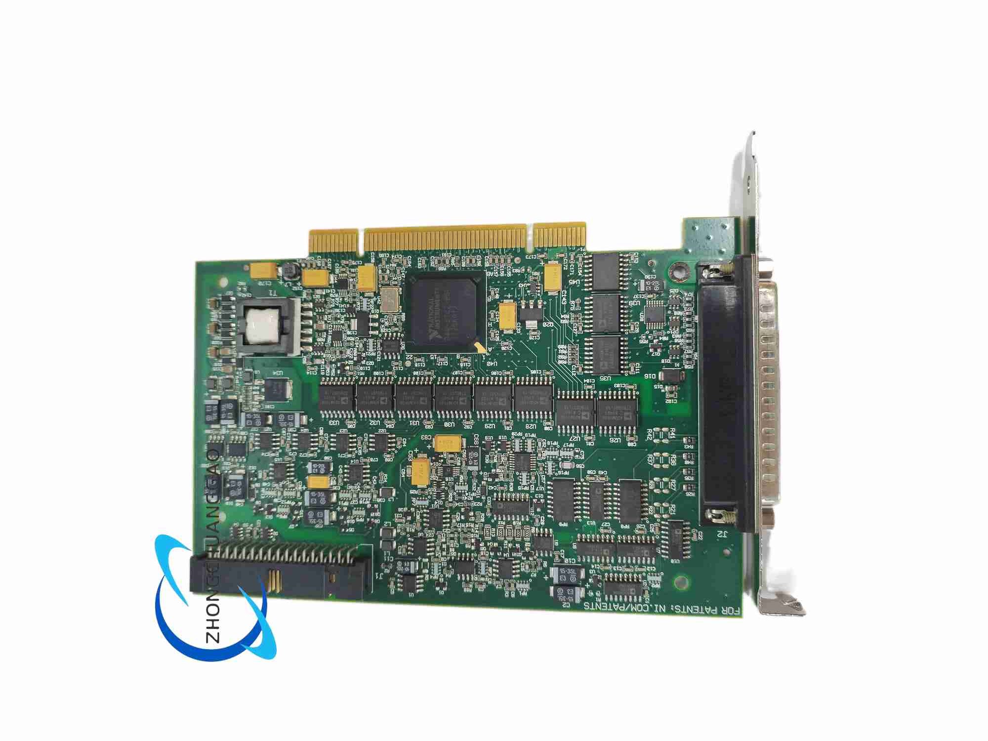
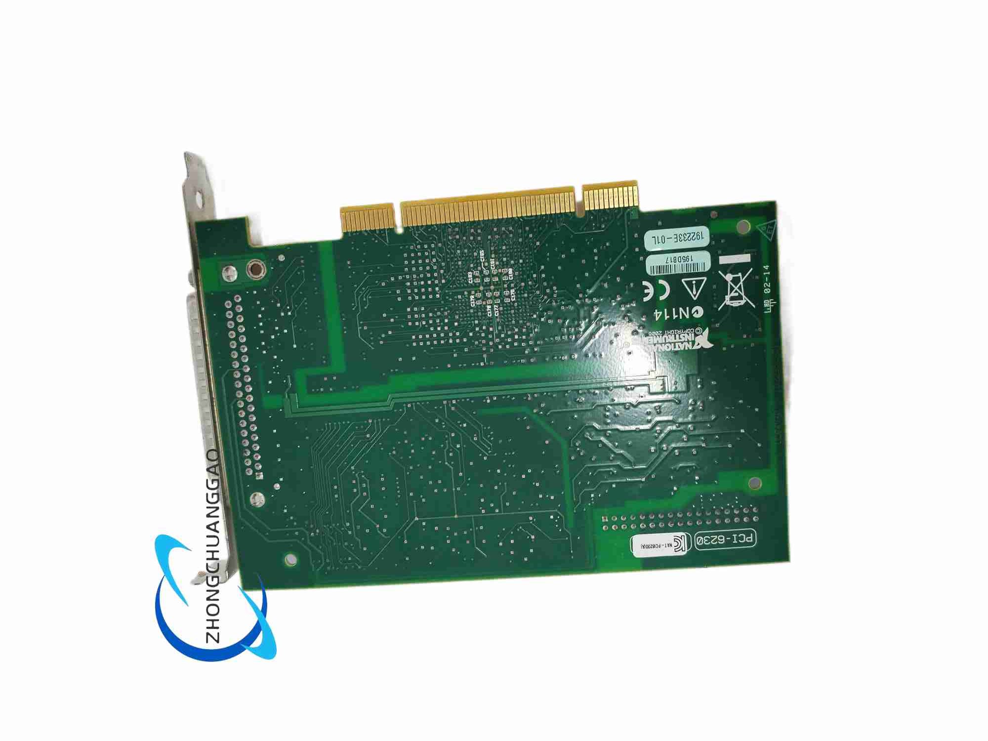
The PCI-6230 is an isolated type M Series multifunction PCI data acquisition board developed by National Instruments, specially designed for industrial field measurement environments with severe ground loop interference, high voltage surge and strong electromagnetic noise. The whole machine adopts full-channel electrical isolation design, integrating multi-channel isolated analog input, isolated analog output, isolated digital I/O and high-resolution counter timer modules, completely eliminating measurement errors caused by industrial ground potential difference and transient high voltage impact.
Description
Isolated Analog Input
- Channel Configuration: 16 single-ended isolated input channels or 8 differential isolated input channels
- ADC Resolution: 16-bit successive approximation analog-to-digital converter
- Maximum Single-channel Sampling Rate: 250 kS/s
- Programmable Isolated Input Voltage Ranges: ±0.1 V, ±0.2 V, ±1 V, ±2 V, ±5 V, ±10 V
- Channel-to-ground Isolation Voltage Rating: 250 Vrms continuous isolation withstand voltage
- Common Mode Rejection Ratio: >120 dB at 50 Hz industrial power frequency interference
Isolated Analog Output
- Channel Count: 4 independent isolated single-ended analog output channels
- DAC Resolution: 16-bit digital-to-analog converter
- Maximum Total Aggregate Output Update Rate: 833 kS/s
- Fixed Isolated Output Voltage Range: ±10 V
- Output Channel Isolation Withstand Voltage: 250 Vrms continuous isolation
Isolated Digital I/O Interface
- Total Digital Channels: 24 bidirectional isolated digital I/O lines divided into three independent 8-bit isolated ports
- Logic Standard: 5 V TTL compatible isolated logic level
- Single Channel Drive Capacity: Maximum 2.4 mA sink and source current
- Digital Port Isolation Withstand Voltage: 250 Vrms continuous isolation between port and ground
Counter & Timer Subsystem
- Counter Quantity: Two independent 32-bit high-resolution isolated event counters
- Maximum Counter Input Frequency: 80 MHz
- Supported Working Modes: Edge counting, frequency measurement, pulse width capture, quadrature encoder position tracking, PWM pulse signal generation
Timing Synchronization System
- Internal Reference Clock Accuracy: ±50 ppm under 25 ℃ standard working temperature
- Multi-board Synchronization: RTSI bus hardware interface supports synchronous clock and trigger signal transmission among multiple isolated M Series DAQ boards
7.4 Functional Features
- Full-channel electrical isolation design for analog input, analog output and digital I/O ports, effectively cutting off ground loop interference caused by different ground potential of industrial field equipment
- 250 Vrms continuous high voltage isolation withstand capability, resisting industrial field transient surge voltage and preventing DAQ board circuit damage
- Dual-mode analog input switching, supporting high-density single-channel measurement and low-noise differential weak signal collection
- Four-channel isolated analog output realizes multi-variable closed-loop control for industrial actuators with different ground potentials
- 24-channel isolated digital I/O ports meet isolated relay control, isolated limit switch detection and isolated digital communication requirements
- 32-bit long counter architecture avoids frequent counter overflow interrupts during long-time continuous pulse signal acquisition
- Complete NI-DAQmx driver compatibility, supporting LabVIEW, Python, MATLAB, C#, C++ mainstream industrial development environments
- Built-in automatic self-calibration function, real-time correcting gain drift and offset error caused by ambient temperature changes
7.5 Application Scenarios
- Heavy industry factory on-site high-voltage equipment temperature, pressure transmitter isolated signal monitoring
- Power distribution cabinet, inverter equipment analog and digital signal isolated collection and control
- Large mechanical equipment multi-point sensor measurement with obvious ground potential difference between equipment and control cabinet
- Energy storage battery pack high voltage loop isolated voltage and current multi-channel synchronous measurement
- Chemical factory explosion-proof area low voltage sensor signal isolated acquisition to avoid ground loop induced signal distortion
- Industrial robot multi-axis motion control isolated analog feedback signal collection
- Railway vehicle electrical equipment on-board isolated multi-sensor data acquisition
7.6 Performance Parameters (Typical under 25℃)
- Continuous Operating Temperature Range: 0 ℃ ~ 55 ℃
- Storage Temperature Range: -40 ℃ ~ 85 ℃
- Peak Total Power Consumption: 19.2 W
- Minimum Warm-up Time to Reach Full Rated Accuracy: 10 minutes continuous power supply
- Maximum Continuous Uninterrupted Working Time: 720 hours without isolation performance attenuation
7.7 Material & Construction Composition
- Main Circuit Substrate: Multi-layer FR-4 high insulation fire-resistant printed circuit board, independent analog isolation area, digital isolation area and host computer communication ground plane, high insulation barrier layout between isolation regions
- Core Processing Chips: 16-bit multi-channel successive approximation ADC, four-channel 16-bit DAC, high isolation linear optocoupler isolation amplifiers, Xilinx dedicated timing control FPGA, dual 32-bit counter logic integrated circuits
- Front Panel Connector: Multi-pin metal shielded D-SUB connector with built-in EMI rubber sealing gasket for all isolated analog, digital and counter wiring terminals
- Mechanical Fixing Components: Cold rolled steel full-height PCI mounting bracket with zinc anti-corrosion electroplating surface treatment
- Passive Electronic Components: High insulation low temperature drift metal film precision resistors, high withstand voltage low noise polypropylene signal capacitors, ferrite magnetic bead EMI suppression components for all input and output signal traces
7.8 Structural Characteristics
- Form Factor: Standard full-length 32-bit 33 MHz PCI bus expansion board
- Physical Overall Dimensions: Width 10.6 cm, Length 17.5 cm
- PCB High-insulation Partition Design: Analog isolation circuit area, digital isolation circuit area and host computer communication non-isolation area separated by wide high-insulation PCB isolation strips to guarantee 250 Vrms isolation withstand voltage performance
- Thermal Dissipation Layout: High-density copper thermal vias laid under FPGA, ADC and DAC high-power chips for passive convection heat dissipation without additional cooling fans
- EMI Shielding Layout: Closed copper ground shielding layer around all non-isolation digital communication traces; each isolated channel independent small shielding ring to prevent cross-channel crosstalk
7.9 Working Principle
- Isolated Analog Input Signal Conditioning Stage: External industrial sensor analog voltage signal enters isolated linear optocoupler isolation amplifier circuit; high insulation optocoupler completely separates industrial field ground potential and host computer board internal ground; software controlled programmable gain circuit amplifies weak sensor signals to match ADC full-scale range; single-ended/differential multiplexer switches signal transmission path according to user configuration
- 16-bit Successive Approximation ADC Conversion: Isolated analog voltage signal is sampled and held; successive approximation ADC completes binary search analog-to-digital conversion and outputs 16-bit binary digital data; converted data is temporarily stored in onboard FIFO buffer memory
- FPGA Timing and Isolated Digital I/O Control Logic: Onboard dedicated FPGA generates programmable sample clock and trigger signals for analog input and output channels; FPGA completes isolated digital port direction switching, digital input filter noise suppression and digital signal transmission control to PCI bus; optocoupler isolation circuit isolates digital signal between industrial field and host computer
- 32-bit Isolated Counter Timer Operation: External industrial pulse, quadrature encoder signals enter isolated counter input optocoupler buffer circuits; 32-bit counter logic accumulates pulse counts, measures input signal frequency and pulse width, and outputs variable frequency digital pulse signals synchronized with board master clock
- Four-channel Isolated Analog Output DAC Conversion: Host computer transmits target analog voltage digital data to onboard DAC FIFO memory; each independent 16-bit DAC converts discrete digital sample values into analog voltage signals, then passes through linear optocoupler isolation circuit to output isolated analog voltage to drive external industrial actuators and test fixtures
- RTSI Multi-board Synchronization Logic: RTSI bus transmits unified master clock and trigger signals between multiple PCI-6230 boards, realizing fully synchronous multi-card multi-channel isolated analog signal collection and isolated analog waveform output
7.10 Installation Requirements
- Host PC Expansion Slot: Unoccupied full-length 32-bit PCI motherboard expansion slot; computer chassis must be equipped with forced air cooling fan to maintain internal temperature within rated operating range
- Pre-operation Warm-up Requirement: After powering on the host computer, maintain continuous power supply for at least 10 minutes before executing high-precision DC voltage measurement tasks to eliminate thermal drift errors
- Mechanical Installation Steps: Remove the metal blank baffle of the chassis expansion slot; align the gold-plated edge connector of the PCI board with the motherboard PCI slot; fully insert the board until the connector is completely seated; tighten the fixing screw of the steel mounting bracket to the chassis frame to eliminate PCB mechanical vibration
- Isolated Signal Wiring Specifications: All isolated analog sensor signal wiring adopts double shielded twisted pair cables; connect the outer shielding layer of the cable to the metal shell of the D-SUB connector to form low-impedance EMI ground reference; strictly separate isolated field signal cables and host computer internal power cables to avoid high voltage breakdown of isolation barriers
- Software Driver Installation Process: Download and install the latest NI-DAQmx driver software matching the host operating system; launch NI MAX hardware configuration tool, the software automatically identifies PCI-6230 isolated DAQ hardware equipment; execute onboard self-calibration program after hardware identification to correct channel gain and offset errors
7.11 Operation Precautions
- Isolation Voltage Limit Restriction: Do not continuously input channel-to-ground voltage exceeding 250 Vrms; excessive voltage will break down internal optocoupler isolation barriers and permanently damage the entire DAQ board
- ESD Static Discharge Protection Rule: Wear a grounded anti-static wristband before touching PCB boards, connectors and internal circuit components; electrostatic discharge will permanently damage sensitive ADC, DAC, FPGA and optocoupler chips
- Chassis Cooling Mandatory Requirement: Do not run PCI-6230 with the side panel of the host computer chassis removed; insufficient air convection will cause serious thermal drift, increased measurement noise and attenuation of isolation withstand voltage performance
- Cable Separation Specification: Strictly separate isolated field signal cables and high-power industrial wiring to prevent high voltage surge from breaking down PCB isolation strips
- Calibration Cycle Regulation: Execute onboard self-calibration every 45 days of continuous operation; complete full external factory calibration with NI certified reference voltage equipment once per calendar year
- Storage Environment Requirements: When uninstalled from the host computer, store PCI-6230 in the original factory anti-static packaging bag; avoid long-term storage in high humidity, dusty and extreme temperature environments; high humidity will reduce PCB isolation resistance and isolation withstand voltage performance
- Digital I/O Current Limit Warning: Do not make single digital channel sink or source current exceed 2.4 mA; excessive current will burn out digital output driver circuits and optocoupler isolation chips permanently
Reviews
There are no reviews yet.