
Product Short Description
Product Name: Bosch Rexroth HED 8 OH-2X/100K14A(A/S) Hydraulic-Electric Plunger-Type Pressure Switch
Product Introduction: The HED8OH-1050K14AS (R901107128 family, type HED 8 OH-2X/100K14A) is a plunger-type hydraulic pressure switch in Bosch Rexroth’s HED 8 series. The “OH” denotes subplate (inline) mounting; “100” denotes a 100 bar pressure rating; “K14” denotes an electrical connection per EN 175301-803 with a 3-pole + PE connector; “A” or “AS” denotes the adjustment type (with or without scale and protective cap). The suffix “1050” corresponds to the 105-mm body length variant.
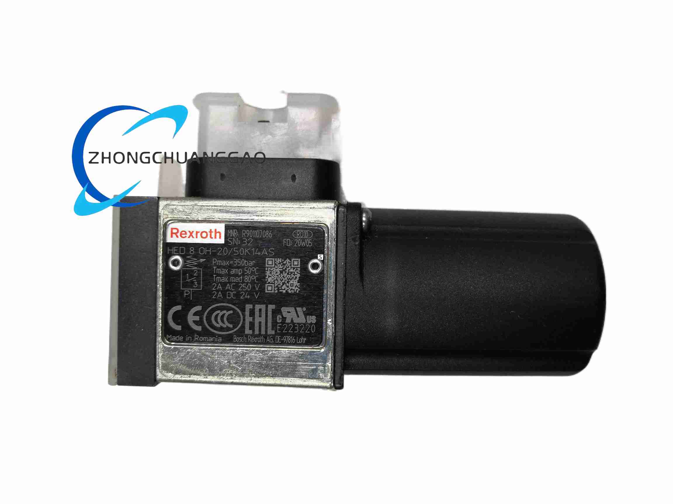
Description
Technical Specifications:
- Pressure Rating: 100 bar (component series 2X)
- Pressure Adjustment Range: 10–100 bar
- Differential per Full Screw Turn: ≈ 35 bar
- Adjustment Types Available: Hex socket adjustment rod without scale (no code); with scale (A); with scale and protective cap (AS); with scale lockable knob (KS/KW)
- Electrical Connection: Connector “K14” per EN 175301-803, 3-pole + PE; alternatively “K35” per IEC 61076-2-101, M12 × 1, A-coded, 4-pole
- Switching Element: Micro-switch with normally closed / normally open contact function
- Zero-current Switching: 1 mA to 2 A
- Max. Switching Frequency: 7200 operations/hour
- Switching Accuracy (repeatability): < 1% of set pressure
- Contact Bounce: < 5 ms (both open and close)
- Transition Resistance: < 50 mΩ
- Insulation Coordination: Overvoltage category 3, pollution degree 3
- Current/Voltage Ratings (Connector K14): 2 A at 250 V AC (AC-12, ohmic); 0.5 A at 250 V DC (DC-12, inductive); 0.2 A at 125 V DC; 0.1 A at 250 V DC
- Current/Voltage Ratings (Connector K35): 2 A at 48 V DC (ohmic); 0.5 A at 48 V DC (inductive)
- Mechanical Life: ≥ 5 million switching cycles
- Hydraulic Oil Temperature Range (NBR seal): -25°C to +80°C
- Hydraulic Oil Temperature Range (FKM seal): -20°C to +80°C
- Viscosity Range: 10–800 mm²/s
- Max. Allowable Oil Contamination: ISO 4406 cleanliness grade 20/18/15
- Ambient Temperature Range: -25°C to +50°C (NBR seal); -20°C to +50°C (FKM seal); -40°C to +50°C (low-temperature seal)
- Mounting Position: Any orientation
- Weight: Approx. 0.8 kg (0.8 mm dimensions per data sheet)
- Vibration Test: DIN EN 60068-2-6: 10–2000 Hz / max. 10 g
- Shock Test: DIN EN 60068-2-27: 15 g / 11 ms
- Compliance: CE, UL 508 (up to 350 bar), CCC GB14048.5-2008, RoHS (EU 2011/65/EU)
Connector & Protection Details:
- With connector “K14”: IP65 (when mating connector properly mounted)
- With connector “K35”: IP67 (when mating connector properly mounted)
- Switching Function (Terminals 1-2): Contact opens upon pressure increase
- Switching Function (Terminals 1-3 / 1-4): Contact closes upon pressure increase (depending on wiring)
Functional Features: Five pressure classes available (50/100/200/350/630 bar) within the HED 8 platform; four adjustment types; direct-acting plunger mechanism translates hydraulic pressure into micro-switch actuation; spring-loaded plunger with adjustable set-point; field-adjustable via hex socket or scaled knob; optional visual indicator (LED) on certain connector variants.
Application Scenarios: Pressure monitoring and limit switching in hydraulic power units; pump start/stop control; over-pressure cut-off for water-cooled condensers in refrigeration systems; pressure sequencing in machine tools; safety interlock for pressure vessels; mobile hydraulic systems.
Structural & Material Characteristics: Body constructed for subplate mounting with G1/4 port (DIN 3852-2); sealing via NBR, FKM, or low-temperature (MT) seals depending on fluid compatibility; 2 × M5-8 mounting screws (metric ISO 4762, M5 × 55, 10.9, tightening torque 6 + 0.5 Nm); plunger and micro-switch housed in a robust metal enclosure; adjustment shaft accessible from the top or side depending on model variant.
Working Principle: Hydraulic pressure acting on the plunger overcomes the adjustment spring force. When the set pressure is reached, the plunger moves and actuates the internal micro-switch, opening or closing the electrical contact. Rotating the adjustment screw clockwise increases the set pressure, counter-clockwise decreases it. The differential (dead-band) between make and break pressure is determined by the mechanical geometry and is approximately proportional to the adjustment screw rotation.
Installation Requirements: Mount on a flat, machined contact surface (surface quality Rz ≤ 1 max, per RE 50061); use the specified 2 × M5 screws with correct tightening torque (6 + 0.5 Nm); select seal material compatible with the hydraulic fluid in use; wire the micro-switch per the required power supply and specific application (terminals 1-2 / 1-3 / 1-4); ensure the mating connector (K14 or K35) is fully seated to achieve the stated IP65/IP67 protection; for refrigeration/condenser applications, connect the drain chamber directly back to the reservoir to avoid excessive back-pressure that would impair sensitivity.
Usage Notes: Select the appropriate pressure class — do not use a high-pressure switch in a low-pressure system, as it impairs sensitivity; after adjusting the set pressure, lock or fix the adjustment position to prevent drift due to vibration; ensure the hydraulic fluid meets the required ISO 4406 cleanliness grade (20/18/15); verify seal compatibility with the fluid (NBR, FKM, or MT) before installation; the pressure switch must be installed per the manufacturer’s requirements; for refrigeration applications, the high-pressure setting is typically 10–11 kg/cm² gauge (with R-12 refrigerant) — adjust accordingly for other refrigerants; do not exceed the electrical ratings of the micro-switch (2 A at 250 V AC max for K14).
Reviews
There are no reviews yet.