
Product Short Description
Product Introduction
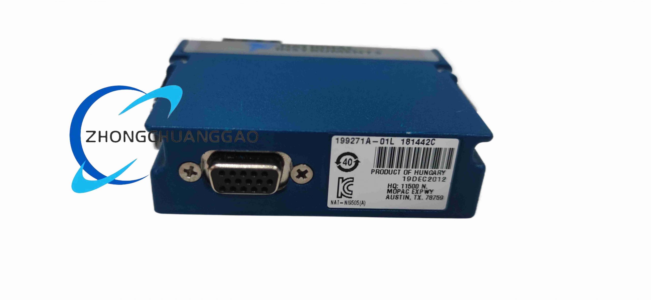
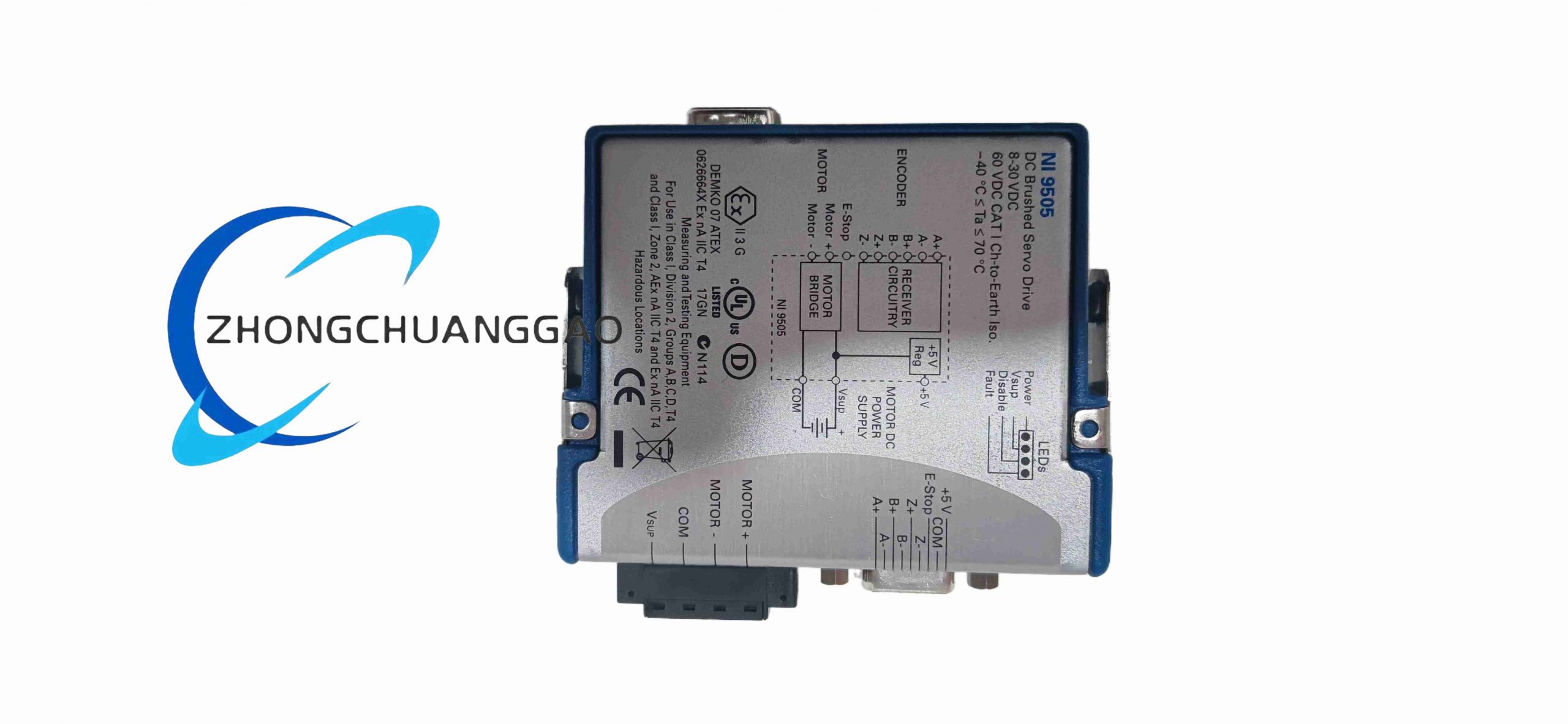
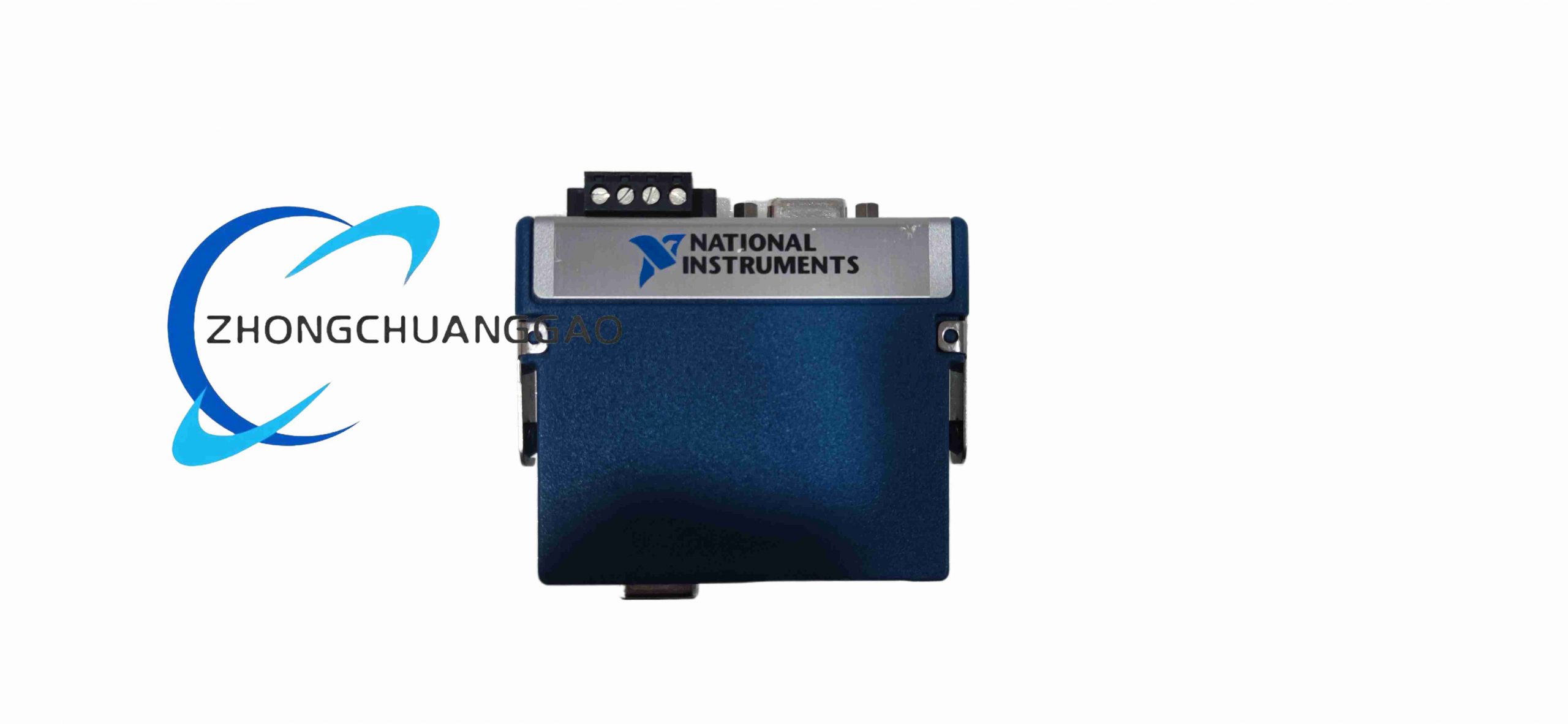
The NI 9505 is a dedicated C Series signal conditioning module built for CompactRIO embedded real-time measurement systems, designed to acquire signals from full-bridge strain gauges, load cells, torque transducers and pressure sensors with built-in programmable excitation power. Every channel integrates independent bridge excitation supply, high-precision instrumentation amplifier and low-pass anti-aliasing filter to eliminate external signal conditioning hardware. This module delivers high-accuracy microstrain measurement for static and dynamic mechanical testing under harsh industrial electromagnetic interference environments.
Description
Core Technical Specifications & Performance Parameters
- Channel Configuration: 4 independent full-bridge measurement channels, each channel electrically isolated from adjacent channels
- Bridge Excitation Output: Programmable DC excitation voltage of 1V, 2.5V, 5V, 10V, short-circuit protection built into each excitation output circuit
- Measurement Bridge Compatibility: Strict full Wheatstone bridge compatible; supports standard 350Ω and 120Ω strain gauge bridges, load cell transducers with internal full-bridge circuits
- Programmable Gain Range: Software selectable gain of 10, 100, 200, 500, 1000 to amplify microvolt-level strain signals
- ADC Resolution & Sampling: 24-bit delta-sigma analog-to-digital converter, maximum aggregate sampling rate of 51.2 kS/s across all 4 active channels
- Input Signal Full Scale Range: ±15 mV/V standard strain measurement range
- Channel Isolation Level: 250 Vrms channel-to-channel galvanic isolation, 600 Vrms channel-to-chassis isolation
- Module Power Consumption: Max 900 mW under full 4-channel continuous measurement mode
- Connector Form: Front panel screw terminal block with secure locking wire clamps
- Environmental Ratings
- Operating temperature: -40℃ ~ +70℃
- Relative humidity: 5% ~ 95% non-condensing
- Shock resistance: 30 g half-sine pulse for 11 ms; vibration resistance: 5 g RMS random vibration
- Protection grade: IP40 when installed inside sealed CompactRIO chassis
Function & Feature Highlights
- Four fully independent isolated full-bridge channels, each equipped with adjustable excitation power supply, eliminating cross-channel signal interference and ground loop drift in multi-load-cell distributed measurement systems
- Multi-level programmable amplifier gain covers ultra-low microstrain signals from precision load cells and high-amplitude strain signals from mechanical test specimens; gain configuration is fully editable via LabVIEW FPGA without hardware modification
- Integrated digital low-pass anti-aliasing filter with configurable cut-off frequency, automatically filters high-frequency industrial noise before analog-to-digital conversion to avoid signal aliasing distortion
- Built-in comprehensive self-diagnosis functions including bridge open-circuit detection, short-circuit excitation protection and wire break alarm; diagnostic fault signals can be transmitted to upper monitoring systems for real-time fault warning
- Native full compatibility with all CompactRIO series real-time industrial controllers; strain signal acquisition, bridge balance calibration and dynamic load calculation logic can be customized and executed deterministically on chassis FPGA chips
- Compact standard C Series modular design allows dense installation alongside temperature, voltage and digital I/O modules on a single CompactRIO chassis to realize integrated multi-physical quantity testing platforms
- Screw-type locking terminal block provides stable wire clamping force; terminals resist loosening under long-term mechanical vibration in production line and test bench environments
Working Principle
The NI 9505 module connects to the CompactRIO chassis through the standard C Series backplane bus, obtaining DC operating power and digital configuration instructions from the chassis real-time processor and FPGA chip. The module’s internal power management circuit generates stable programmable DC excitation voltage, which is output to external full-bridge strain gauges or load cells through front panel wiring terminals. When external mechanical load generates deformation on the strain gauge, the resistance value of each bridge arm changes proportionally, creating a tiny differential microvolt voltage output signal from the full bridge circuit. This weak differential signal is transmitted back to the module’s input terminal, first passing through a high-input-impedance buffer circuit to prevent signal attenuation caused by long field wiring resistance. The buffered signal enters a programmable gain instrumentation amplifier, which amplifies the microvolt-level differential signal to a voltage range matching the input limit of the 24-bit delta-sigma ADC chip. The amplified analog signal is filtered by a configurable low-pass anti-aliasing filter to remove high-frequency electromagnetic noise generated by on-site motors and frequency converters. The filtered analog signal is sampled and converted to high-precision digital strain data by the delta-sigma ADC. Raw digital measurement data is temporarily stored in the onboard FIFO buffer memory, then transmitted to the CompactRIO chassis FPGA chip through the high-speed backplane bus. Users run customized LabVIEW FPGA logic to perform automatic bridge balance zero calibration, microstrain conversion, load force/torque calculation, real-time data filtering and threshold over-load alarm judgment. The channel-by-channel isolation transformer inside the module completely isolates the strain signal circuit of each channel to block common-mode voltage interference generated by different ground potentials of field sensors. When the internal monitoring circuit detects bridge wire breakage or excitation short-circuit faults, it immediately cuts off the excitation power supply of the faulty channel and sends a digital fault alarm signal to the chassis control system.
Material Composition & Structural Features
- Housing Material: Black flame-retardant UL94-V0 industrial ABS plastic shell, impact-resistant structural reinforcement ribs integrated inside the shell
- Isolation Structure: Independent miniature isolation transformers equipped for each measurement channel, high-insulation dielectric filling between transformer windings to meet 250 Vrms isolation requirements
- Internal Circuit Board: Multi-layer low-noise analog-digital mixed signal PCB, separate analog ground plane and digital ground plane to prevent digital switching noise from contaminating weak strain analog signals
- Core Electronic Components: Low-noise JFET input buffer operational amplifiers, programmable gain instrumentation amplifiers, 24-bit delta-sigma ADC chips, digital low-pass filter processing chips, adjustable DC excitation power management chips, channel ESD and overvoltage TVS protection diodes
- Chassis Mounting Structure: Standard C Series horizontal slide rail locking structure; the module slides into the empty I/O slot of the CompactRIO chassis, and the metal locking buckle at the rear is clamped to the edge of the chassis slot to ensure tight contact between the module edge connector and the chassis backplane gold fingers under continuous mechanical vibration
- Front Panel Terminal Assembly: Plastic screw terminal block with metal locking screws, thick copper conductive terminals with anti-oxidation gold-plated surface treatment
Installation Requirements
- Chassis Mounting Steps: Slide the NI 9505 module horizontally into the empty C Series I/O slot of the CompactRIO industrial controller chassis, push the module completely backward until the rear locking buckle clicks to lock, ensuring full electrical contact between the module connector and the chassis backplane bus
- Field Sensor Wiring Specifications
- Cable Selection: Use shielded four-core twisted-pair dedicated strain gauge cable for all full-bridge load cell and strain gauge wiring; the metal shielding layer of the cable is single-end grounded inside the control cabinet to suppress external electromagnetic induction noise
- Terminal Wiring Operation: Strip 6 mm insulation from the end of the copper wire, insert the stripped metal wire into the terminal clamping cavity, tighten the metal locking screw clockwise until the wire cannot be pulled out by hand to avoid loose contact under vibration
- Bridge Wiring Sequence: Strictly follow the module wiring diagram to connect the four bridge arms of the strain gauge to the corresponding excitation positive, excitation negative, signal positive and signal negative terminals of the same channel; cross-channel wiring is prohibited to avoid measurement errors
- Environmental Installation Restrictions
- The CompactRIO chassis equipped with the NI 9505 module must be installed inside a fully sealed indoor industrial electrical control cabinet; installation positions with direct water splashing, corrosive chemical gas, conductive metal dust or direct high-temperature heat radiation are forbidden
- Maintain a minimum spacing of 30 mm between the NI 9505 module and high-power heat-generating components such as power supply modules and frequency converters inside the cabinet to avoid excessive ambient temperature affecting strain measurement accuracy
- High-Vibration Environment Installation Rules
- For mechanical production lines, engine test benches and other long-term high-vibration working environments, use cable ties to fix all strain sensor cables to the cabinet internal wiring brackets to prevent wire pulling and terminal loosening
- Regularly check the tightness of terminal locking screws every quarter to eliminate unstable signal noise caused by loose wiring
- Altitude Operation Limits: The module supports stable continuous operation at altitudes up to 2000 meters above sea level; for high-altitude industrial test sites above 2000 meters, additional heat dissipation fans need to be installed inside the control cabinet to reduce ambient operating temperature
Application Scenarios
- Automotive component durability test benches: Chassis load testing, suspension compression strain measurement, engine torque transducer signal acquisition
- Material mechanical performance laboratory testing: Tensile testing machines, compression testing machines, bending fatigue test equipment full-bridge strain data collection
- Industrial weighing and force monitoring systems: Tank load cell weight monitoring, hoist lifting force real-time measurement, hydraulic cylinder thrust closed-loop control
- Aerospace component environmental testing: Aircraft structural fatigue strain monitoring, landing gear impact force measurement, composite material thermal-mechanical coupling strain testing
- Metallurgical and heavy machinery production lines: Rolling mill roll pressure detection, stamping equipment mold impact force monitoring, bridge structure distributed strain health monitoring
- Wind power equipment testing: Wind turbine blade fatigue strain measurement, gear box torque real-time monitoring, tower structural load long-term data logging
Operation & Maintenance Precautions
- All field sensor wiring modification, terminal disassembly and module replacement operations must be performed after completely cutting off the main DC power supply of the CompactRIO chassis; transient voltage surges generated by live wiring will permanently damage the internal high-precision strain measurement amplifier circuit
- Do not connect the excitation output terminals of the module to external voltage power supplies; reverse voltage input will burn the internal excitation power management chip and render the measurement channel permanently invalid
- Before starting formal strain measurement every time, complete automatic bridge balance zero calibration through LabVIEW FPGA software; zero drift caused by temperature changes and wire resistance differences must be eliminated before collecting formal test data
- Avoid long-term continuous operation when the ambient temperature of the cabinet exceeds +70℃; excessive high temperature will increase thermal noise of the analog measurement circuit and cause significant zero drift of strain measurement results
- During scheduled annual equipment maintenance, use dry compressed air to blow away dust accumulated on the module shell and front terminal block; dust accumulation will cause terminal oxidation and unstable signal transmission
- When replacing a faulty NI 9505 module, confirm that the chassis power supply is completely disconnected before sliding out the faulty module; after installing a new spare module, re-download the LabVIEW FPGA measurement program and re-calibrate the zero balance of each measurement channel before restarting the test system
Reviews
There are no reviews yet.