
Product Short Description
Product Overview
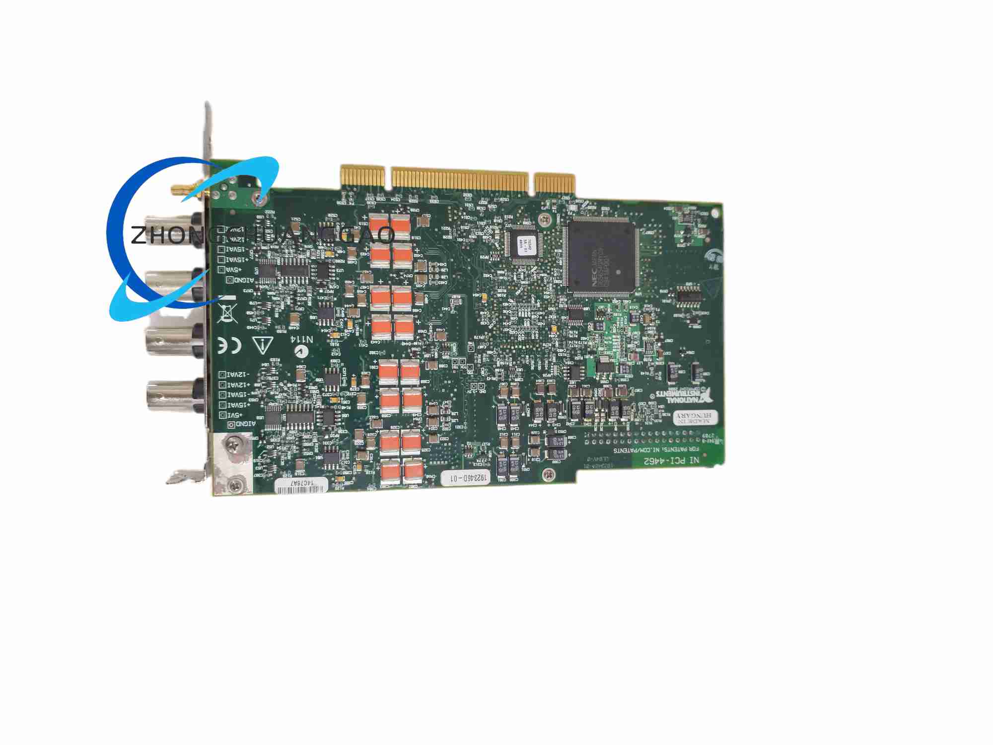
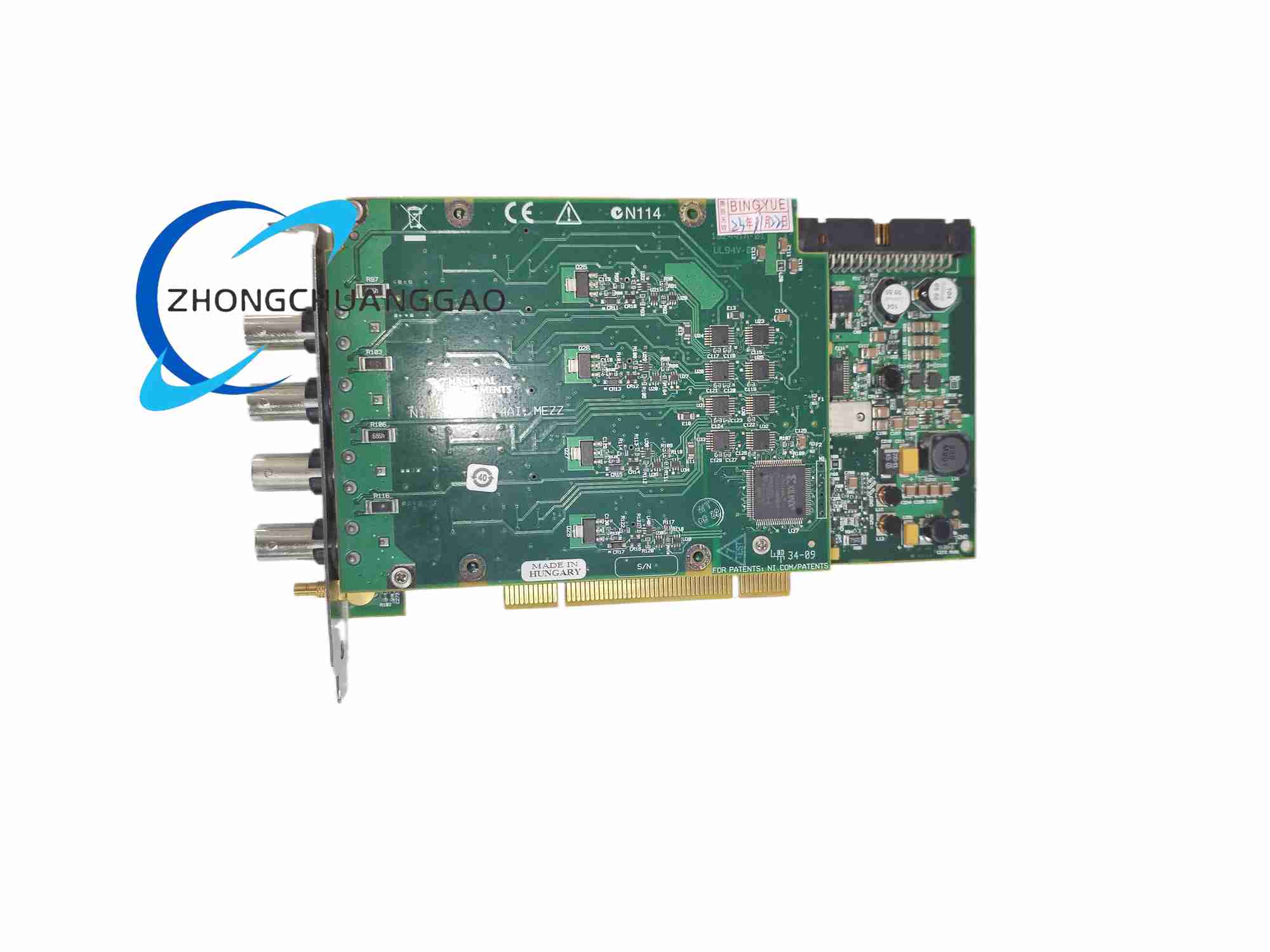
The PCI-4462 is an enhanced high-precision dynamic signal PCI board designed for vibration and acoustic testing with integrated IEPE sensor excitation current sources. It features four synchronous differential analog input channels and two synchronous analog output channels, all utilizing 24-bit high-resolution delta-sigma converters for ultra-low noise microvolt-level signal capture..
Description
Analog Input (AI)
- Channel Count: 4 independent differential synchronous sampling channels
- ADC Resolution: 24-bit delta-sigma converter
- Sampling Rate Range: 1 kS/s to 204.8 kS/s, 181.9 µS/s step resolution
- Input Configuration: Software-selectable true differential or pseudodifferential (50 Ω shield-to-chassis ground)
- Coupling Mode: Per-channel independent AC/DC coupling
- Integrated IEPE Excitation: Software-controlled 4 mA constant current source per channel, 0–24 V compliance voltage for industrial accelerometers
- Full-Scale Input Voltage Ranges: ±42.4 V (-20 dB), ±31.6 V (-10 dB), ±10 V (0 dB), ±3.16 V (+10 dB), ±1 V (+20 dB)
- Anti-Aliasing Bandwidth: 93 kHz full-channel simultaneous bandwidth
- Inter-Channel Crosstalk: < -95 dB
- Dynamic Range: 113 dBFS at 0 dB attenuation, 102.5 kS/s sampling rate
Analog Output (AO)
- Channel Count: 2 differential synchronous output channels
- DAC Resolution: 24-bit delta-sigma modulator
- Update Rate Range: 1 kS/s to 204.8 kS/s
- Minimum Load Impedance: 600 Ω
- Short-Circuit Protection: Indefinite positive/negative output short-circuit protection
- Amplitude Flatness: ±0.008 dB from 20 Hz to 20 kHz; ±0.1 dB from 20 Hz to 92.1 kHz
- THD Performance: -97 dBc below 20 kHz
Timing & Clock
- Internal Timebase Accuracy: ±20 ppm across full operating temperature range
- Synchronization Support: RTSI bus multi-card phase-locked synchronization; external 10 MHz reference clock input
2.4 Functional Features
- Native IEPE sensor constant current excitation eliminating external signal conditioning modules for accelerometer testing
- 24-bit ultra-high resolution ADC/DAC for microvolt-level low-noise signal measurement
- Four fully synchronous input channels for multi-point structural vibration mapping
- Per-channel independent gain, coupling and IEPE excitation configuration for mixed-sensor test setups
- Combined analog/digital anti-imaging filters on output channels for clean stimulus waveform generation
- Built-in self-calibration algorithm to automatically correct temperature-induced offset and gain errors
- NI-DAQmx driver compatibility with LabVIEW, MATLAB, Python, C# and C++ development environments
- Programmable digital trigger input/output for external test fixture synchronization
2.5 Application Scenarios
- Aerospace aircraft cabin noise and structural vibration wind tunnel testing
- Automotive engine, suspension and transmission vibration durability testing
- Industrial rotating machinery predictive maintenance vibration monitoring
- Structural modal analysis of buildings, bridges and mechanical frames
- Precision acoustic testing of loudspeakers, microphones and audio transducers
- Shock and impact signal measurement for crash test simulation equipment
2.6 Performance Parameters (Typical at 25°C)
- Minimum Detectable Signal: 1.25 µV RMS at maximum input gain
- Operating Temperature Range: 0 °C to 55 °C
- Storage Temperature: -40 °C to 85 °C
- Peak Power Consumption: 22.7 W
- Warm-Up Time for Full Accuracy: 15 minutes continuous power operation
2.7 Material & Construction Composition
- Base PCB: Multi-layer FR-4 high-Tg fire-resistant circuit board with separate analog, digital and power ground planes
- Core Signal ICs: 24-bit multi-channel delta-sigma ADC/DAC, low-noise JFET input operational amplifiers, Xilinx FPGA timing and data processing controller
- Front Panel Connector: Multi-channel shielded metal D-SUB connector with integrated EMI suppression gaskets
- Retention Hardware: Zinc-plated cold-rolled steel full-height PCI mounting bracket
- Passive Components: Ultra-low drift metal film resistors, low-loss polypropylene signal capacitors, ferrite EMI suppression beads on all input/output traces
2.8 Structural Characteristics
- Form Factor: Standard full-length 32-bit PCI bus compliant expansion board
- Physical Dimensions: 10.6 cm width × 17.5 cm length
- PCB Zone Isolation: Strict physical separation of analog front-end circuitry and digital FPGA/PCI bus circuits via copper ground guard rails to minimize switching noise coupling
- Thermal Design: High-density copper thermal vias under high-power FPGA and ADC chips for passive convection heat dissipation
- EMI Shielding: Continuous copper ground shield layer surrounding all analog signal traces to block external electromagnetic interference
2.9 Working Principle
- Sensor Input Conditioning Stage: External IEPE accelerometer or voltage transducer signal enters per-channel differential buffer circuit; software enables constant 4 mA IEPE excitation current for piezoelectric sensors; programmable gain stage amplifies low-level signals, AC/DC coupling capacitors filter DC bias as required
- 24-Bit Delta-Sigma Analog-to-Digital Conversion: Oversampled delta-sigma ADC converts analog voltage to high-resolution digital data; built-in digital low-pass filters suppress out-of-band aliasing noise before decimating samples to user-defined sampling frequency
- FPGA Timing & Data Buffering: Onboard FPGA generates synchronized sample clock signals for all input and output channels; digitized waveform data is temporarily stored in onboard FIFO memory before high-speed data transfer over PCI bus to host PC RAM
- Arbitrary Waveform Digital-to-Analog Conversion: Host PC transmits pre-defined arbitrary or standard waveform data to onboard output FIFO; 24-bit delta-sigma DAC interpolates digital waveform data with multi-stage digital filters, converting digital samples to smooth continuous analog stimulus voltage
- Multi-Channel Synchronization Logic: RTSI bus interface shares high-precision clock and trigger signals across multiple PCI-4462 boards, enabling fully phase-aligned simultaneous multi-card measurement systems
2.10 Installation Requirements
- Host PC Hardware Slot: Full-length unoccupied 32-bit PCI motherboard expansion slot; PC chassis must support active forced-air cooling to maintain rated temperature operating range
- Pre-Operation Warm-Up: Power on host PC and maintain continuous power for 15 minutes prior to precision measurement tasks to eliminate thermal drift errors
- Mechanical Mounting Procedure: Remove chassis slot blank metal plate; align PCI board gold edge connector with motherboard PCI slot; fully insert connector until seated; secure steel retention bracket screw tightly to chassis frame to eliminate mechanical vibration of the PCB
- Signal Wiring Specifications: Use double-shielded twisted-pair coaxial cable for all analog sensor connections; connect cable outer shielding to front panel D-SUB metal shell to establish low-impedance EMI ground reference; separate analog signal wiring from high-current power, motor and digital control cables by minimum 15 cm distance
- Software & Driver Installation: Download and install latest NI-DAQmx driver package compatible with Windows/Linux host operating system; launch NI MAX hardware configuration utility to automatically detect PCI-4462; execute full onboard self-calibration routine immediately after hardware detection
2.11 Operation Precautions
- Input Overvoltage Protection Limit: Do not apply analog input voltage exceeding ±42.4 V peak; excessive voltage will permanently damage front-end JFET amplifier circuits
- ESD Static Discharge Prevention: Mandatory grounded anti-static wristband usage before physical contact with PCB, connectors or internal circuit components; electrostatic discharge irreparably damages high-sensitivity 24-bit ADC/DAC chips
- Chassis Cooling Mandate: Never operate PCI-4462 with host PC chassis side panel removed; insufficient convection airflow causes severe thermal drift, reduced dynamic range and inaccurate measurement data
- Cable Segregation Rules: Maintain physical separation between low-level analog sensor cables and high-power industrial wiring to avoid electromagnetic interference-induced signal noise
- Calibration Maintenance Schedule: Execute onboard self-calibration every 30 days of continuous operation; complete full external factory calibration with NI certified reference signal equipment once per calendar year
- Storage Environment Requirements: When uninstalled from host PC, store PCI-4462 in original factory anti-static shielding packaging; avoid long-term storage in high-humidity, dusty or extreme temperature environments
- IEPE Sensor Wiring Caution: Verify correct sensor wiring polarity before enabling IEPE constant current excitation; reversed polarity wiring will cause loss of measurement signal and potential sensor damage
Reviews
There are no reviews yet.