
Product Short Description
Product Overview
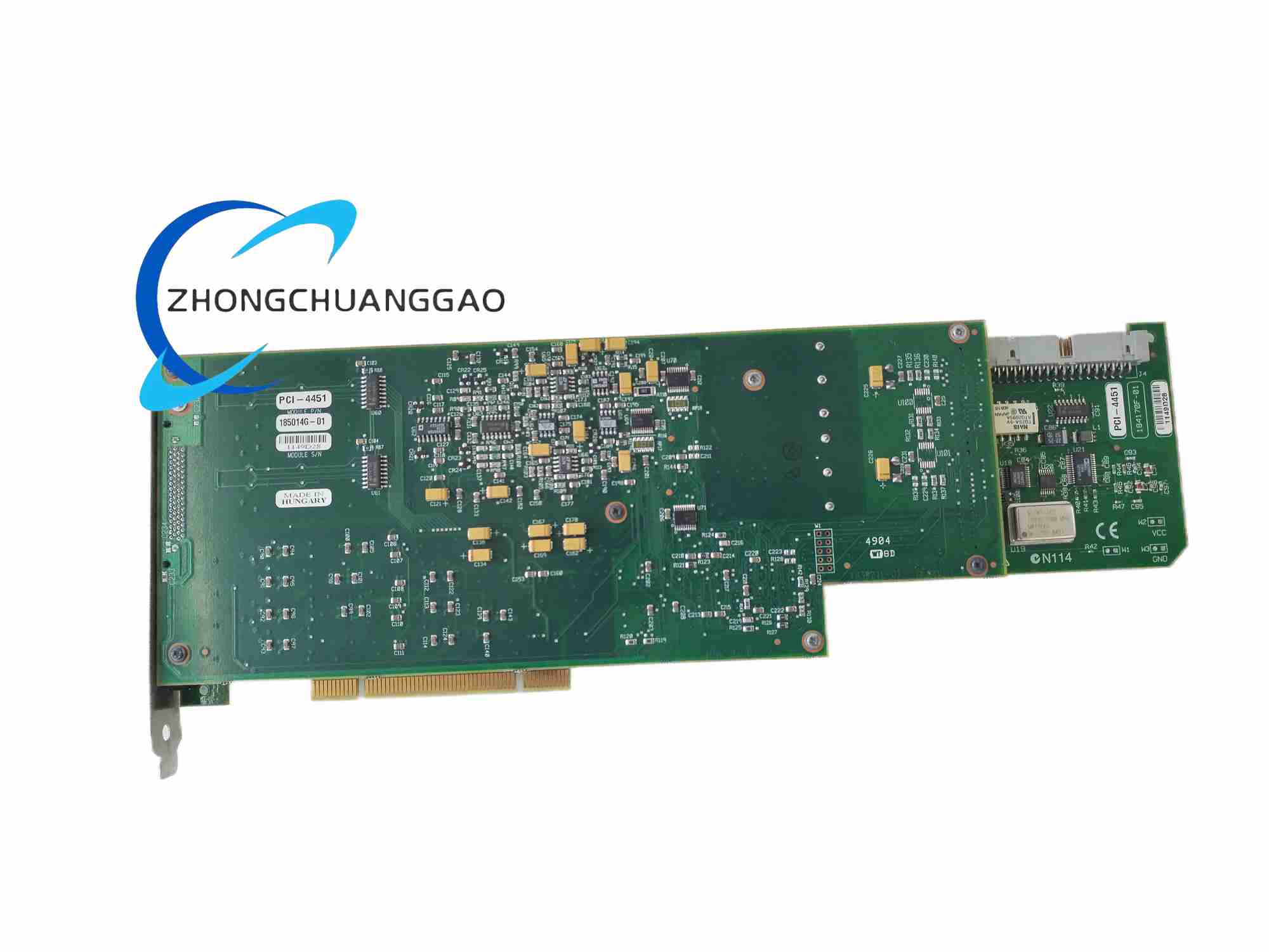
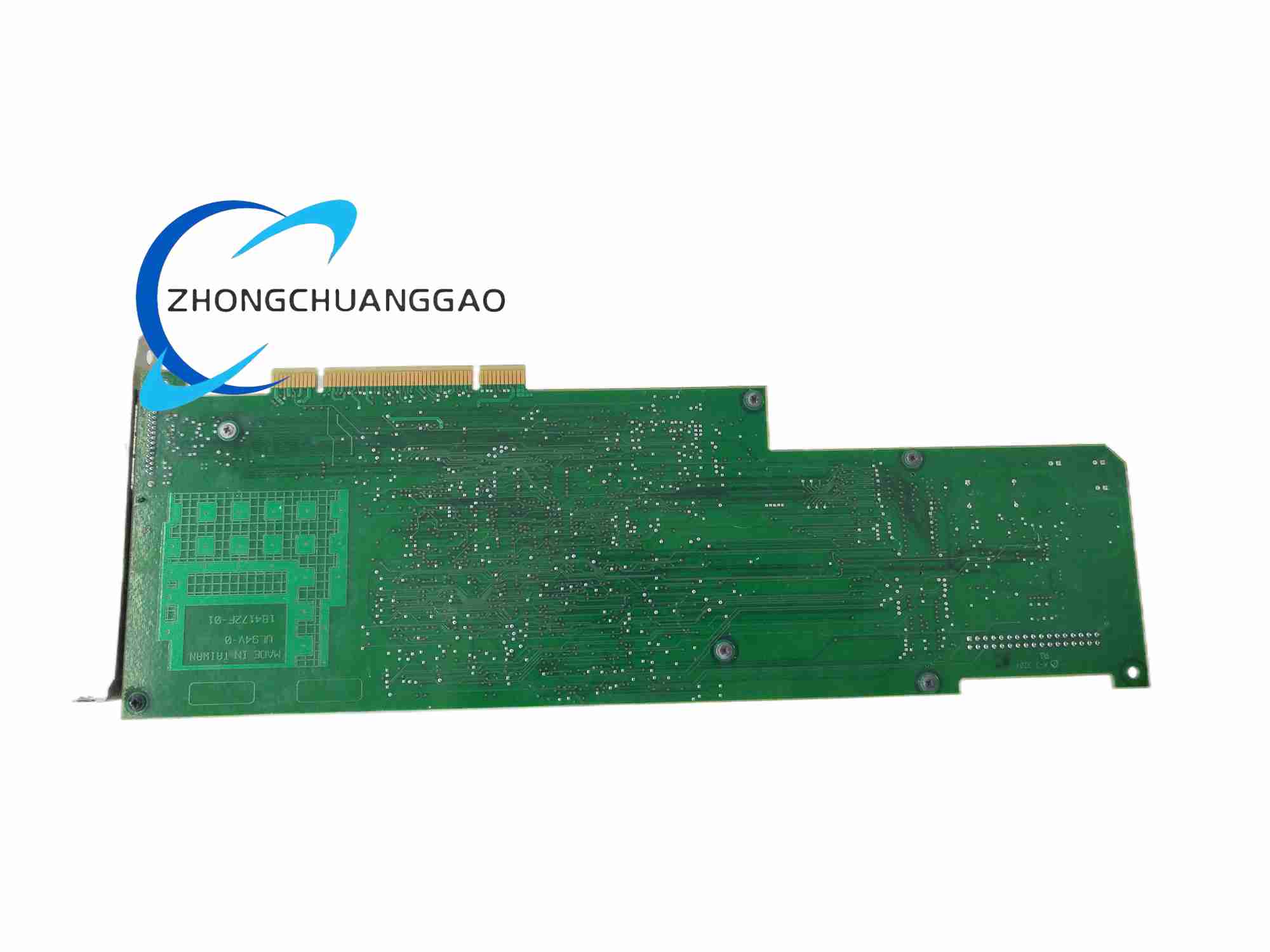
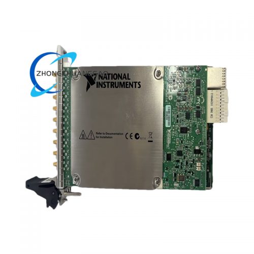
The PCI-4451 is a National Instruments PCI-bus dynamic signal analyzer board dedicated to acoustic, vibration and frequency response testing. It integrates synchronous analog input and analog output channels for simultaneous stimulus-response measurement. The device uses delta-sigma ADC/DAC architecture to deliver ultra-low noise and high dynamic range for low-level transducer signals including microphones and accelerometers
Description
Analog Input (AI)
- Channel Count: 2 true differential synchronous sampling channels
- ADC Resolution: 16-bit delta-sigma converter, 128x oversampling
- Sampling Rate Range: 5 kS/s to 204.8 kS/s, adjustable in 190.735 µS/s increments
- Input Voltage Ranges (Software Selectable Gain): ±42.4 V (-20 dB), ±31.6 V (-10 dB), ±10 V (0 dB), ±3.16 V (+10 dB), ±1 V (+20 dB)
- Anti-Aliasing Bandwidth: 45 kHz
- Inter-Channel Crosstalk: < -90 dB
- Dynamic Range: 114 dB
Analog Output (AO)
- Channel Count: 2 differential synchronous output channels
- DAC Resolution: 16-bit delta-sigma modulator with 8x interpolation oversampling
- Update Rate Range: 1.25 kS/s to 51.2 kS/s
- Programmable Output Attenuation: 0 dB, -20 dB, -40 dB
- Amplitude Flatness: ±0.2 dB from DC to 23 kHz
- Total Harmonic Distortion (THD): -90 dB at 1 kHz
Timing & Clock
- Internal Timebase Accuracy: ±100 ppm at 25 °C
- Multi-Board Synchronization: RTSI bus support for phase-locked multi-card acquisition
1.4 Functional Features
- Simultaneous AI/AO operation for closed-loop frequency response testing
- True differential input architecture eliminates common-mode industrial noise
- Built-in analog + digital anti-imaging filters on output channels to suppress spurious harmonics
- Software-selectable AC/DC input coupling for low-frequency static and high-frequency dynamic signals
- Multi-level programmable gain to match microphones, IEPE accelerometers and voltage transducers
- Self-calibration routine to correct offset and gain drift over temperature changes
- Full NI-DAQmx driver support with LabVIEW, Python, C/C++ programming APIs
1.5 Application Scenarios
- Acoustic noise measurement for household appliances, automotive interiors
- Mechanical vibration testing of motors, bearings, gearboxes
- Frequency response analysis of speakers, sensors, structural components
- Audio equipment distortion and noise performance verification
- Small-scale wind tunnel dynamic pressure signal acquisition
1.6 Performance Parameters (Typical at 25°C)
- Input Noise Floor: < 1.2 µV RMS at maximum gain
- Settling Time: < 1 µs for full-scale voltage step
- Operating Temperature Range: 0 °C to 55 °C
- Storage Temperature: -40 °C to 85 °C
- Power Consumption: 18.2 W peak
1.7 Material & Construction Composition
- Main Substrate: FR-4 fire-retardant printed circuit board with copper trace shielding layers
- Signal Processing ICs: Multi-channel delta-sigma ADC/DAC chips, low-noise operational amplifiers, FPGA timing controller
- Front Panel Connector: Shielded D-SUB multi-pin metal connector with EMI gasket
- Mechanical Bracket: Cold-rolled steel PCI full-height retention bracket with corrosion-resistant zinc plating
- Passive Components: Low-temperature-drift metal film resistors, polypropylene low-noise signal capacitors
1.8 Structural Characteristics
- Form Factor: Standard full-length PCI bus board (32-bit PCI 33 MHz)
- Physical Dimensions: 10.6 cm width × 17.5 cm length
- Layout Design: Isolated analog and digital PCB zones separated by ground guard rings to minimize digital switching noise leakage to analog signal paths
- Thermal Layout: Copper thermal vias under high-power FPGA and ADC chips for passive heat dissipation
- EMI Suppression: Full perimeter copper ground shielding around all analog signal traces
1.9 Working Principle
- Signal Input Stage: External transducer analog voltage enters true differential input buffer; software-controlled gain amplifies weak sensor signals, with AC/DC coupling capacitor network to block DC offset when required
- Analog-to-Digital Conversion: Delta-sigma ADC samples analog input at oversampled high frequency, filters quantization noise to high-frequency bands, then decimates data to user-defined sampling rate for digital signal processing
- Digital Timing & Synchronization: Onboard FPGA generates precise sample clock, trigger signals and RTSI synchronization pulses; FPGA buffers digitized waveform data before PCI bus data transfer to host PC memory
- Digital-to-Analog Conversion: Host PC uploads arbitrary waveform data to onboard FIFO memory; delta-sigma DAC interpolates low-rate waveform data with digital filters, converts digital samples back to continuous analog voltage for stimulus output
- Closed-Loop Measurement Logic: Synchronized input sampling and output waveform generation enable simultaneous stimulus injection and response capture for transfer function calculation
1.10 Installation Requirements
- Host PC Slot: Unoccupied full-length 32-bit PCI expansion slot; PC chassis must support forced air cooling to maintain operating temperature limits
- System Pre-Warm-Up: Power on host PC and allow 15 minutes of warm-up time before precision measurement to reach rated accuracy specifications
- Mechanical Installation: Remove chassis slot blank plate; align PCI board edge connector with motherboard PCI slot; fully seat connector, fasten steel retention bracket screw to chassis frame
- Wiring Installation: Use shielded twisted-pair cable for all analog signal connections; connect cable shield to front panel D-SUB metal shell to establish EMI ground reference
- Software Installation: Install NI-DAQmx driver suite matching operating system; launch NI MAX configuration utility to detect PCI-4451 hardware and complete self-calibration
1.11 Operation Precautions
- Voltage Input Protection: Do not apply input voltage exceeding ±42.4 V peak; overvoltage will permanently damage front-end amplifier circuits
- ESD Handling: Wear grounded anti-static wristband before touching PCB or connectors; static discharge destroys sensitive ADC/DAC chips
- Cooling Maintenance: Never operate the board with PC chassis side panel removed; insufficient airflow causes thermal drift and automatic measurement inaccuracy
- Cable Management: Separate analog signal cables from power supply, motor drive and digital control wiring to avoid electromagnetic interference
- Calibration Cycle: Execute self-calibration every 30 days of continuous operation; perform full external calibration annually with NI certified reference signal sources
- Storage Rules: When not installed in host PC, store PCI board in original anti-static packaging at room temperature; avoid high-humidity and dusty storage environments
Reviews
There are no reviews yet.