Product Short Description
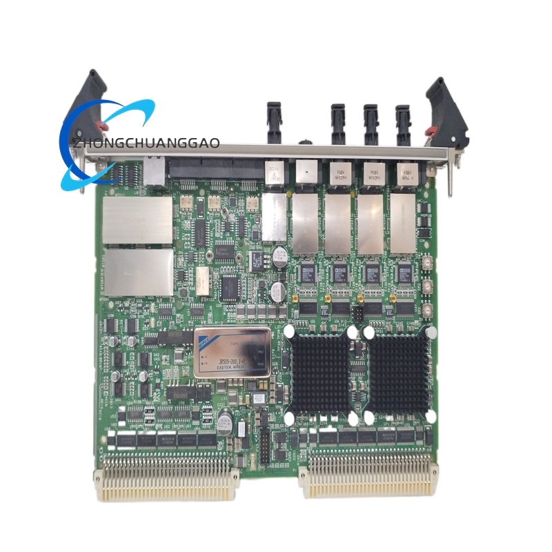
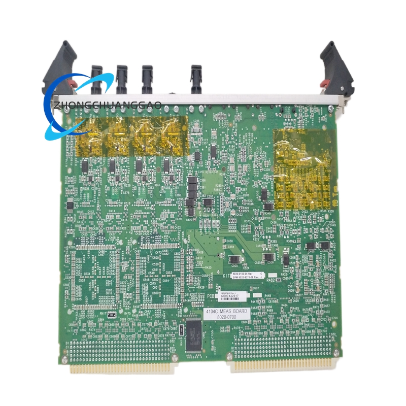
The Zygo 4104C is a high-precision, computer-controlled Fizeau laser interferometer engineered for sub-nanometer surface metrology. It is the flagship model within the Zygo GPI (General Purpose Interferometer) XP product line, designed for production-floor and laboratory-grade optical surface testing. The system measures surface figure, flatness, sphericity, asphericity, radius of curvature, power, step height, and optical thin-film thickness with extreme accuracy. It replaces manual fringe analysis with fully automated, software-driven data acquisition and interpretation.
Description
Model Series
| Model | Series | Primary Application |
|---|---|---|
| 4104C | GPI XP | General-purpose high-accuracy surface metrology |
| 4100 | GPI | Legacy general-purpose interferometer |
| 7500 | GPI LT | Large-aperture, long-range metrology |
| 4500 | Verifire | Asphere and freeform metrology |
| 5500 | Laser Fizeau | High-speed production interferometer |
Technical Specifications
| Parameter | Value |
|---|---|
| Laser Wavelength | 632.8 nm (HeNe, frequency-stabilized) |
| Laser Type | Single-mode, frequency-stabilized Helium-Neon (HeNe) |
| Laser Power Output | 1.5 mW (typical) |
| Detector | 16-bit CCD camera array (1360 × 1024 pixels, typical) |
| Aperture Range (Selectable) | 25 mm, 50 mm, 75 mm, 100 mm, 150 mm, 200 mm, 300 mm |
| Z-Axis Scan Range | 50 mm (standard), up to 100 mm (extended) |
| Z-Axis Resolution | 0.1 nm |
| Surface Figure Accuracy | λ/200 RMS (typical), λ/100 RMS (standard specification) |
| Repeatability | λ/1000 RMS |
| Dynamic Range | >100,000:1 |
| Measurement Speed | Full-aperture acquisition in 1–5 seconds |
| Spatial Resolution | Diffraction-limited by aperture size |
| Environmental Sensitivity | Compensated via internal air refractive index correction |
| Reference Surface | Integrated high-precision Fizeau reference flat/sphere (transmission type) |
| Reference Surface Quality | λ/20 PV (typical) |
| Computer Interface | USB 3.0 / Gigabit Ethernet |
| Operating System Compatibility | Windows 10/11 (64-bit) |
| Power Supply | 100–240 VAC, 50/60 Hz, single-phase |
| System Dimensions (Typical 300mm) | Approximately 600 mm × 500 mm × 400 mm (L × W × H) |
| System Weight (Typical 300mm) | Approximately 45 kg |
Functional Features
- Full-aperture surface figure measurement in a single acquisition
- Flatness testing with PV and RMS output
- Sphericity and asphericity measurement using Zernike polynomial decomposition
- Radius of curvature (ROC) determination for both concave and convex surfaces
- Optical power measurement (PV, RMS, best-fit sphere, best-fit parabola)
- Step height measurement for coated or uncoated optical components
- Thin-film thickness measurement using fringe-counting algorithms
- Automated alignment via computer-controlled tip/tilt and translation stages
- Pass/Fail analysis with user-defined tolerances
- 3D surface map generation with color-coded deviation plots
- Zernike polynomial analysis up to 36th order (standard), expandable to 72nd order
- Time-series / vibration analysis capability
- Multi-wavelength mode for resolving ambiguity in step-height measurements
- Data export in multiple formats: PDF, CSV, ZMX, DAT, BMP, TXT
Performance Parameters
| Parameter | Specification |
|---|---|
| Surface Figure Accuracy (RMS) | λ/200 (typical), λ/100 (guaranteed) |
| Repeatability (RMS) | λ/1000 |
| Peak-to-Valley (PV) Accuracy | λ/10 (typical) |
| Dynamic Range | >100,000:1 |
| Lateral Resolution | Determined by aperture; 25 mm aperture ≈ 25 μm pixel size |
| Vertical Resolution | 0.1 nm (Z-axis encoder) |
| Measurement Uncertainty (k=2) | <1 nm RMS for high-quality optics |
| Stray Light Rejection | >60 dB |
| Polarization Sensitivity | <0.5% |
| Temperature Drift (compensated) | <0.5 nm/°C after correction |
Material Composition
| Component | Material |
|---|---|
| Optical Bench / Base | Cast iron with epoxy granite composite damping |
| Reference Surface (Flat) | Fused silica substrate, super-polished, ion-beam-sputtered (IBS) coated |
| Reference Surface (Sphere) | Fused silica or Zerodur substrate, super-polished |
| Beamsplitter Cube | UV-grade fused silica, dielectric-coated |
| Mirror Substrates (internal) | Fused silica, λ/10 PV surface quality |
| Housing / Enclosure | Anodized aluminum alloy (6061-T6) |
| Optical Mounts | Stainless steel (303/316), Invar where thermal stability is critical |
| Cable Harness | Shielded, EMI-rated |
| Vibration Isolation | Passive pneumatic isolators (standard), optional active isolation |
Structural Features
- Fizeau interferometer optical configuration: laser beam splits at a beamsplitter, one path reflects off the internal reference surface, the other off the test surface; recombined beams create interference fringes
- Transmission-type reference flat/sphere: light passes through the reference surface twice, doubling sensitivity and eliminating back-reflection errors
- Computer-controlled 5-axis alignment stage: X, Y, Z translation plus tip and tilt for automated positioning
- Integrated CCD camera: mounted at the output port of the interferometer, captures full-aperture fringe pattern in a single frame
- Z-axis piezoelectric scanner: provides sub-nanometer vertical displacement for phase-shifting interferometry (PSI)
- Enclosed optical path: sealed housing minimizes air turbulence and dust contamination
- Air refractive index compensation sensor: built-in temperature, pressure, and humidity sensors feed real-time corrections into the measurement algorithm
- Touchscreen or PC-based control interface: MetroPro software runs on a dedicated Windows workstation
- Modular aperture turret: allows switching between aperture sizes without realignment (on select configurations)
Working Principle
- A frequency-stabilized HeNe laser at 632.8 nm emits a coherent beam
- The beam enters a beamsplitter cube and divides into two paths:
- Reference path: reflects off the internal high-precision reference surface (flat or sphere)
- Test path: reflects off the surface under test (SUT)
- The two beams recombine at the beamsplitter and form an interference fringe pattern
- The CCD camera captures the fringe pattern across the full aperture
- Phase-shifting interferometry (PSI): the Z-axis piezo scanner moves the reference surface in precise steps (typically 4 or 5 steps), capturing multiple frames to extract the phase map
- The MetroPro software processes the phase data to reconstruct a 3D surface map of the SUT
- The software calculates PV, RMS, Zernike coefficients, power, radius of curvature, and other parameters relative to a user-selected reference (best-fit sphere, best-fit plane, etc.)
- Air refractive index corrections are applied in real time using measured environmental conditions
Advantages and Highlights
- Sub-nanometer vertical resolution (0.1 nm) with full-aperture coverage
- λ/200 RMS surface figure accuracy — industry-leading for production metrology
- λ/1000 RMS repeatability ensures measurement consistency across repeated tests
- Full-aperture acquisition in seconds — dramatically faster than point-by-point profilometers
- Automated alignment eliminates operator skill dependency
- Zernike polynomial decomposition enables direct comparison to optical design specifications
- Pass/Fail with tolerance overlay supports production-line quality control
- Non-contact measurement — zero force applied to the optic under test
- Environmentally compensated — internal sensors correct for air index variations
- MetroPro software provides complete analysis, archiving, and reporting in one package
- Modular aperture system supports multiple optic sizes on a single instrument
- Long-term stability — frequency-stabilized laser eliminates wavelength drift
Applicable Industries
| Industry | Application |
|---|---|
| Optical Manufacturing | Lens and mirror surface figure verification |
| Semiconductor Lithography | Projection lens and reticle metrology |
| Aerospace and Defense | High-precision mirror and window testing |
| Laser Systems | Laser cavity mirror and gain medium flatness |
| Telecommunications | Fiber optic connector and filter surface testing |
| Astronomy | Telescope primary and secondary mirror figure |
| Medical Optics | Endoscope lens and surgical optic inspection |
| Automotive Optics | Headlamp lens and HUD combiner metrology |
| Metrology Laboratories | National standards and calibration labs |
| Thin-Film Coating | Coating thickness and uniformity verification |
| Freeform Optics | Custom aspheric and freeform surface characterization |
Installation Requirements
| Requirement | Specification |
|---|---|
| Floor Load Capacity | Minimum 200 kg/m² |
| Table Surface | Rigid, level optical table or granite slab; vibration amplitude <0.1 μm |
| Ambient Temperature | 20 °C ± 1 °C (recommended); operational range 18–25 °C |
| Relative Humidity | 30%–60% RH (non-condensing) |
| Cleanliness | ISO Class 7 or better (Class 10,000) recommended |
| Electrical Supply | 100–240 VAC, 50/60 Hz, single-phase, 2 A maximum, grounded outlet |
| EMI Environment | No high-power RF sources within 2 meters; shielded cable recommended |
| Vibration Isolation | Pneumatic isolators required; active isolation recommended for sub-nanometer work |
| Space Clearance | Minimum 1.0 m clearance on all sides for access and airflow |
| Network Connectivity (optional) | Ethernet port for data archiving to network storage |
Usage Precautions
- Never look directly into the laser beam — 632.8 nm HeNe laser is Class 2/3R; direct eye exposure causes retinal damage
- Do not touch optical surfaces (reference or test) with bare fingers — use lint-free gloves or handles
- Allow 30-minute warm-up time before precision measurements for laser frequency stabilization
- Keep the interferometer enclosure closed during measurement to prevent air currents from distorting fringes
- Do not exceed the specified aperture size for the installed reference surface — using a larger optic than the aperture causes vignetting and measurement error
- Clean optics only with approved solvents (methanol or isopropanol) and lint-free wipes; never use acetone on coated surfaces
- Avoid thermal shock — do not place hot or cold optics directly onto the stage; allow thermal equilibration
- Do not operate in environments with excessive vibration (>0.5 μm amplitude) — this degrades fringe contrast and measurement accuracy
- Perform regular reference surface calibration using certified reference flats/spheres at intervals defined by the quality system
- Store the system in a clean, dry, temperature-controlled environment when not in use
- Do not disassemble the sealed optical head — internal alignment is factory-set and requires certified service
- Update MetroPro software to the latest version for improved algorithms and bug fixes
- Log all environmental conditions (temperature, pressure, humidity) at time of measurement for traceability
Software Package
| Software | Function |
|---|---|
| MetroPro | Primary analysis software — surface map, Zernike, PV/RMS, pass/fail, 3D visualization, data export |
| Mx™ Software (optional) | Advanced asphere and freeform analysis module |
| ** GageCap (optional)** | SPC statistical process control integration |
| Zygo Link (optional) | Remote diagnostics and system health monitoring |
Key Parameters Summary (Bold Reference)
| Field | Value |
|---|---|
| Laser Wavelength | 632.8 nm (HeNe) |
| Surface Figure Accuracy | λ/200 RMS (typical), λ/100 RMS (spec) |
| Repeatability | λ/1000 RMS |
| Dynamic Range | >100,000:1 |
| Z-Axis Resolution | 0.1 nm |
| Aperture Options | 25 mm / 50 mm / 75 mm / 100 mm / 150 mm / 200 mm / 300 mm |
| Detector | 16-bit CCD, 1360 × 1024 pixels |
| Zernike Order | Up to 36th order (expandable to 72nd) |
| Measurement Speed | 1–5 seconds per full aperture |
| Reference Surface Quality | λ/20 PV |
| Operating Temperature | 18–25 °C (recommended 20 ± 1 °C) |
Reviews
There are no reviews yet.