
Description
Product Brief Introduction
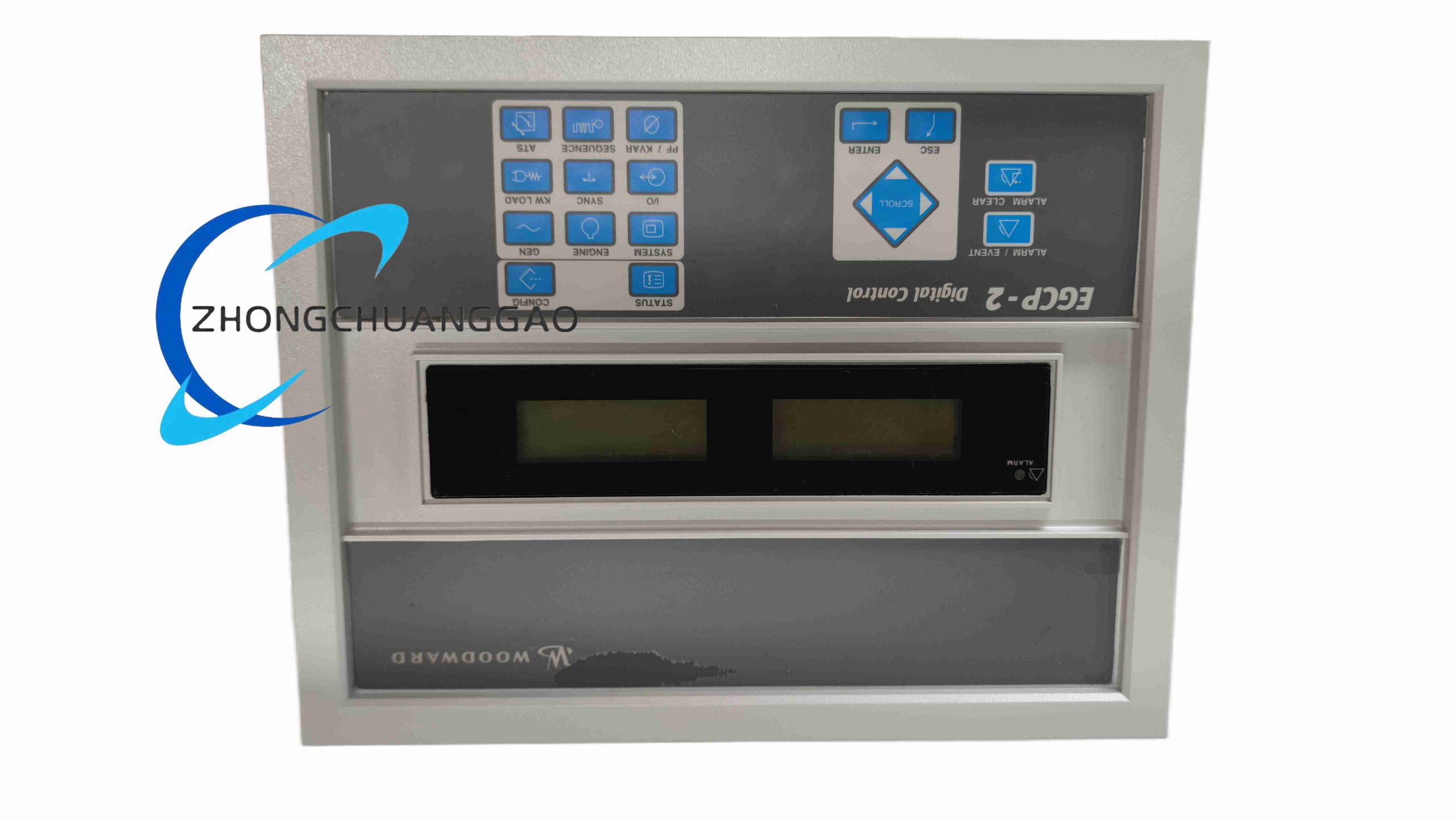
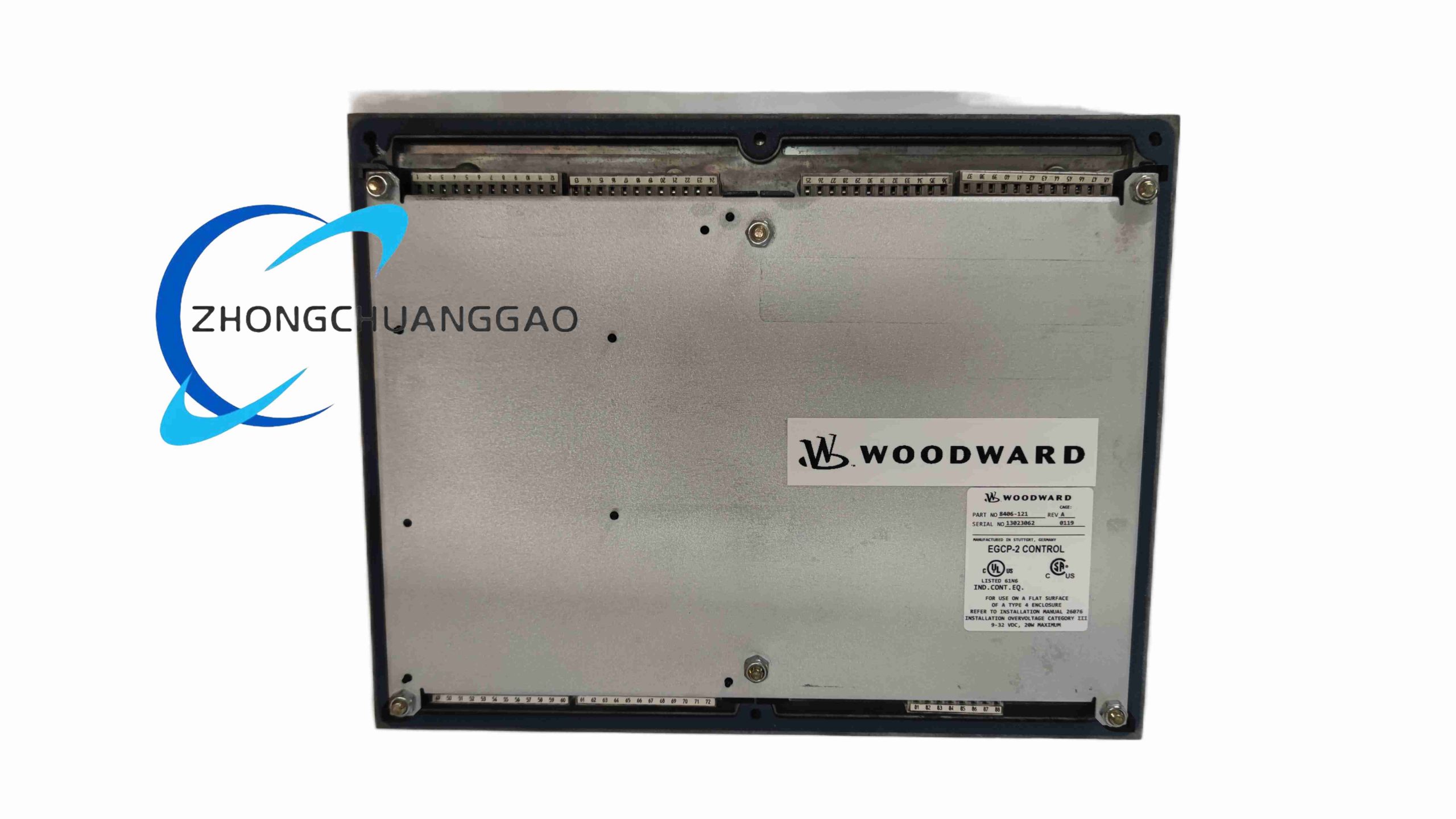
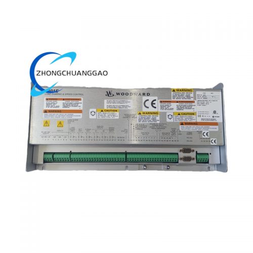
Woodward EGCP-2 (8406-121) is a compact rack-mount integrated control unit dedicated to single or parallel generator sets fueled by diesel, natural gas, dual gas-diesel fuel mixtures. It unifies engine speed governing, generator voltage regulation, full electrical fault protection, breaker synchronization, load sharing and local/remote monitoring functions in a single hardware unit. This model is engineered for stationary standby gensets, prime power generation and cogeneration units, supporting standalone operation, mains parallel tie-in and multi-generator fleet synchronous load distribution without auxiliary external PLC modules.
Core Technical Specifications
- Power Supply Parameters
- Rated Operating Input Voltage: 12 V DC / 24 V DC Wide Range (9 V DC ~ 36 V DC)
- Maximum Continuous Power Consumption: 22 W
- Electrical Measurement Hardware
- Voltage Measurement Input Range: 120 V AC ~ 600 V AC direct input, compatible with PT voltage transformers for high-voltage gensets
- Current Transformer Input Standard: 5 A AC secondary rated CT input
- Supported Operating Frequency: 50 Hz / 60 Hz factory configurable, bandwidth 40 Hz – 72 Hz
- Voltage Measurement Accuracy: ±0.75% full scale at 25 °C nominal temperature
- Active Power Measurement Accuracy: ±1.25% under rated voltage/current operating state
- I/O Channel Configuration
- Digital Isolated Inputs: 16 channels, 24 V DC sink/source universal signal compatibility
- Analog Sensor Inputs: 4 channels for coolant temperature, lube oil pressure, fuel level, exhaust temperature transmitters
- Relay Outputs: 10 form-C changeover relay contacts, each rated 5 A resistive load at 250 V AC
- Communication Interfaces
- RS485 Serial Port: Modbus RTU Master/Slave, CAN bus for inter-unit genset load sharing
- Ethernet RJ45 Port: 10/100 Mbps, Modbus TCP for SCADA remote monitoring
- Mechanical & Environmental Parameters
- Mounting Method: Panel embedded mounting
- Front Panel Cutout Dimension (W × H × D): 234 mm × 160 mm × 86 mm
- Operating Ambient Temperature: -30 °C ~ +70 °C
- Storage Temperature: -40 °C ~ +85 °C
- Altitude Rating: Full performance retention up to 3500 m above sea level without performance derating
- Humidity Tolerance: 5% ~ 95% RH, non-condensing environment only
- Front Panel Protection Grade: IP54; rear wiring compartment IP20
Function Characteristics
- Integrated dual-fuel control algorithm, automatic fuel ratio switching for gas-diesel dual-fuel engine operation with stable speed stability under variable load fluctuations
- Complete generator electrical protection logic: overvoltage, undervoltage, overfrequency, underfrequency, reverse power, overload, short circuit, negative sequence current protection with configurable delay trip timers
- Full engine mechanical protection: overspeed shutdown, low lube oil pressure trip, high coolant temperature trip, emergency stop hard interlock input
- Zero-droop and isochronous dual speed regulation modes for standalone and parallel grid-connected genset applications
- CAN bus inter-unit communication enables synchronous active/reactive load sharing between up to 16 parallel generator units
- Automatic mains failure (AMF) sequence logic: mains loss detection, automatic genset startup, breaker closing, mains recovery controlled cool-down shutdown
- Built-in non-volatile event recorder storing 1000 timestamped fault, alarm and operational cycle logs; real-time trend curve recording of voltage, current, power and frequency
- Front panel monochrome LCD with physical navigation keys for local parameter modification, fault viewing and manual genset operation without external software
Performance Advantages Highlights
- All-in-one integrated design eliminates separate governor, voltage regulator and protection relay hardware, reducing total system component count and wiring complexity
- Ultra-wide DC power input range tolerates large voltage fluctuations from lead-acid engine batteries during cranking and charging cycles
- Dual fuel native control function eliminates third-party fuel conversion controllers for natural gas/diesel hybrid power units
- IP54 sealed front panel withstands dust and light water splashes inside power generation station control rooms
- Independent hardware protection circuits separate from main control CPU; protection trip functions remain active upon main processor communication failure
- Compatible with Woodward ToolKit PC configuration software for one-click parameter backup, upload and standardized genset project template loading
Material Composition & Structural Features
- Front Panel Housing: UV-resistant high-impact ABS plastic with silicone sealing gasket for IP54 environmental isolation
- Main Enclosure Body: Cold-rolled steel sheet with anti-corrosion phosphate primer and matte black finish
- Internal Circuit Board: Multi-layer FR4 industrial PCB with isolated analog measurement plane and digital control plane to suppress electromagnetic cross interference
- Wiring Terminals: Screw-clamp high-current terminal blocks for CT/PT power measurement wiring, low-current spring terminals for sensor and digital signal circuits
- Heat Dissipation Structure: Passive convection grille layout, fanless design to eliminate mechanical fan failure points in continuous running power station environments
Working Principle
Voltage transformers and current transformers feed real-time generator and mains AC voltage/current analog signals to EGCP-2 analog sampling circuits. The internal dual-core microprocessor calculates frequency, phase difference, active/reactive power and compares all measured values against user-programmable protection setpoints. When mains power loss or load demand changes are detected, the unit outputs analog speed control signals to engine fuel actuators and excitation signals to generator AVR to adjust speed and output voltage. For parallel genset systems, CAN bus transmits load distribution data between multiple EGCP-2 controllers to equalize unit power output. Upon detection of mechanical or electrical fault conditions, independent hardware relay circuits immediately open generator breaker contacts and trigger engine shutdown interlocks, while recording fault timestamps and operating parameters to onboard flash memory for maintenance traceability. All operational data is simultaneously transmitted via Ethernet Modbus TCP to central power plant SCADA monitoring systems.
Applicable Industries
Industrial factory standby power stations, natural gas cogeneration plants, remote mining prime power gensets, commercial building backup power, hospital critical load uninterruptible generation, agricultural biogas power generation, marine auxiliary generator control, data center backup diesel/gas gensets, mobile rental generator fleets
Installation Mandatory Requirements
- Mounting Rule: Embed into control cabinet front panel; reserve minimum 45 mm rear clearance for wiring and passive heat convection
- CT Wiring Mandate: CT secondary wiring must form fully closed loops at all times; install short-circuit terminal blocks for CT circuit maintenance to avoid lethal open-circuit high voltage
- Power Supply Wiring: Connect 12/24 V engine battery power with reverse polarity protection fuse (5 A slow-blow) at control unit input terminals
- CAN Bus Load Sharing Wiring: Use shielded twisted-pair CAN cable; mount 120 Ω termination resistor at the two extreme ends of the genset parallel bus network
- Grounding Specification: Connect unit chassis dedicated PE terminal to power cabinet main earth bar with minimum 2.5 mm² copper conductor
- Cabinet Environment Standard: Install within IP40 or above sealed cabinet; prevent continuous oil mist, corrosive gas or direct water spray contacting rear wiring terminals
Operation & Maintenance Precautions
- Complete measurement calibration with precision power analyzer every 12 months to maintain rated voltage and power measurement accuracy
- Backup all controller parameter files via Woodward ToolKit software before any on-site parameter adjustment to prevent configuration loss during accidental power interruption
- Replace internal RTC backup lithium battery every 4 years to avoid timestamp corruption of fault event logs
- Do not energize CT secondary terminals without closed wiring loops; open CT circuits generate dangerous kilovolt-range voltage and permanently damage analog measurement circuits
- Ambient operating temperature exceeding +70 °C causes speed regulation instability and protection trip misoperation; install cabinet cooling fans for high-temperature engine room environments
- Erase historical fault logs only after full data export to external storage to retain regulatory compliance power generation operation records
Reviews
There are no reviews yet.