Product Short Description
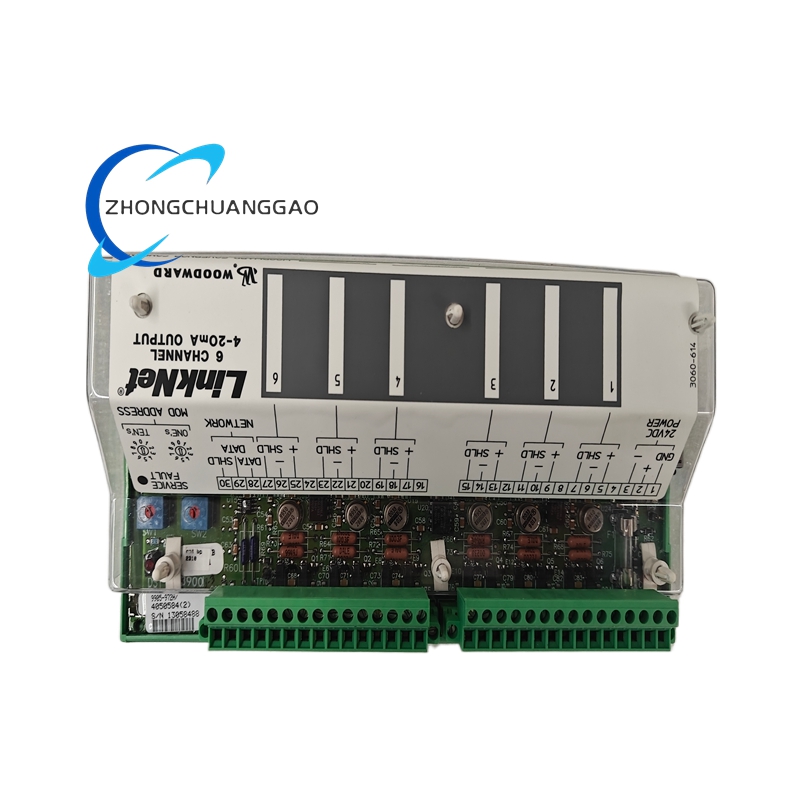
The Woodward 9905-972 is a high-performance microprocessor-based digital governor and automatic voltage regulator (GAVR) controller designed for large industrial gas turbine and diesel generator sets in hazardous (classified) areas. It is part of the Woodward EasyGen 9900 Series, the premium-tier genset control platform engineered for power generation, oil and gas, marine, and mining applications where intrinsic safety certification is mandatory. The 9905-972 integrates speed governing (governor) and voltage regulation (AVR) into a single compact unit, eliminating the need for separate governor and AVR hardware.
Description
Model Series
| Model | Series | System Voltage | Key Variant |
|---|---|---|---|
| 9905-972 | EasyGen 9900 | 24 VDC | High-Output, Dual-Channel, Modbus RTU, IS Barrier Compatible |
| 9905-971 | EasyGen 9900 | 24 VDC | High-Output, Single-Channel, Modbus RTU |
| 9905-962 | EasyGen 9900 | 24 VDC | Low-Output, Dual-Channel, Modbus RTU |
| 9905-961 | EasyGen 9900 | 24 VDC | Low-Output, Single-Channel, Modbus RTU |
| 9905-952 | EasyGen 9900 | 12 VDC | High-Output, Dual-Channel, Modbus RTU |
| 9905-951 | EasyGen 9900 | 12 VDC | High-Output, Single-Channel, Modbus RTU |
| 9905-942 | EasyGen 9900 | 120 VAC | High-Output, Dual-Channel, Modbus RTU |
| 9905-941 | EasyGen 9900 | 120 VAC | High-Output, Single-Channel, Modbus RTU |
| 9905-932 | EasyGen 9900 | 240 VAC | High-Output, Dual-Channel, Modbus RTU |
| 9905-931 | EasyGen 9900 | 240 VAC | High-Output, Single-Channel, Modbus RTU |
| 9905-922 | EasyGen 9900 | 24 VDC | Standard, Dual-Channel, CAN Bus |
| 9905-921 | EasyGen 9900 | 24 VDC | Standard, Single-Channel, CAN Bus |
| 9905-912 | EasyGen 9900 | 24 VDC | Standard, Dual-Channel, EtherNet/IP |
| 9905-911 | EasyGen 9900 | 24 VDC | Standard, Single-Channel, EtherNet/IP |
| 9905-902 | EasyGen 9900 | 24 VDC | Base, Dual-Channel, Modbus RTU |
| 9905-901 | EasyGen 9900 | 24 VDC | Base, Single-Channel, Modbus RTU |
| 9900-100 | EasyGen 9900 | 24 VDC | Legacy analog GAVR (predecessor) |
| 9910-100 | EasyGen 9910 | 24 VDC | Legacy digital GAVR (predecessor) |
| 5500-100 | EasyGen 5500 | 24 VDC | Non-IS, standard GAVR (economy) |
| 5466-100 | EasyGen 5466 | 24 VDC | Non-IS, standard GAVR (economy) |
Technical Specifications
| Parameter | Value |
|---|---|
| Controller Type | Microprocessor-Based Digital Governor + AVR (GAVR) Controller |
| Output Configuration | High-Output (HO) — up to 10 A DC continuous per channel |
| Number of Channels | 2 channels (dual-channel barrier interface) |
| System Voltage | 24 VDC nominal (18 VDC to 32 VDC operating range) |
| Engine Type Supported | Gas turbine, diesel engine, dual-fuel (gas/diesel), steam turbine |
| Generator Size Range | 100 kW to 10,000 kW (134 HP to 13,400 HP) |
| Speed Sensing Input | Magnetic pickup (MPU), 5–30 VAC, 100 Hz to 10 kHz |
| Voltage Sensing Input | 3-phase, 120 VAC to 690 VAC (line-to-line), 45 Hz to 65 Hz |
| Speed Control Mode | Isochronous (0% droop) or Droop (1% to 10% selectable) |
| Speed Setpoint Range | 500 RPM to 3,600 RPM (adjustable via keypad or software) |
| Speed Regulation Accuracy | ±0.05% of setpoint (isochronous), ±0.1% (droop mode) |
| Voltage Setpoint Range | 90 VAC to 130 VAC (adjustable) |
| Voltage Regulation Accuracy | ±0.5% of setpoint (typical), ±0.25% (optimal) |
| Exciter Output Current (HO) | Up to 10 A DC continuous per channel (20 A total) |
| Exciter Output Voltage | Up to 300 VDC maximum per channel |
| Governor Actuator Output | 0–10 VDC or 4–20 mA (proportional, configurable) |
| Response Time (Speed) | <50 ms for 100% load step |
| Response Time (Voltage) | <30 ms for 100% load step |
| Intrinsic Safety Certification | ATEX, IECEx, FM, CSA, TIIS |
| Gas Group Classification | IIA, IIB, IIC (T1 to T6) |
| Dust Group Classification | IIIA, IIIB, IIIC (T85°C to T135°C) |
| Zone Rating (Gas) | Zone 1, Zone 2 |
| Zone Rating (Dust) | Zone 21, Zone 22 |
| Temperature Class | T1 to T6 (gas), T85°C to T135°C (dust) |
| Enclosure Rating | IP65 (front panel), IP20 (rear terminals) |
| Operating Temperature | -25°C to +70°C (-13°F to +158°F) |
| Storage Temperature | -40°C to +85°C (-40°F to +185°F) |
| Communication Interface | RS-485 Modbus RTU (default), optional CAN, EtherNet/IP, USB |
| Analog Outputs | 2 × 4–20 mA or 0–10 VDC (configurable) |
| Digital Inputs | 12 × dry contact (NO/NC), 24 VDC |
| Digital Outputs (Relays) | 6 × programmable relay outputs (NO/NC), 250 VAC / 5 A |
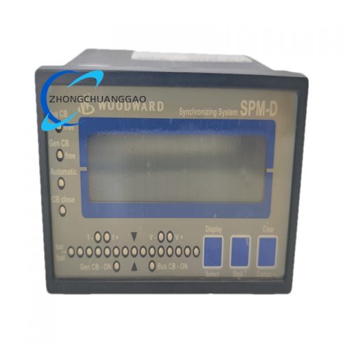
| Display | 240 × 128 pixel color LCD with backlight, touchscreen capable |
| Mounting | 35 mm standard DIN rail (EN 60715) or panel mount |
| Dimensions (Approx.) | 200 mm × 150 mm × 140 mm (H × W × D) |
| Weight (Approx.) | 2.8 kg (6.2 lbs) |
| Certifications | UL 508, CE, CSA, IEC 61000-6-2, IEC 61000-6-4, ISO 8528, ATEX Zone 1/2, IECEx, FM Class I Div 1 Gr A-D, CSA Class I Div 1 Gr A-D, TIIS, SIL 2 |
| Protection Rating | IP65 (front), IP20 (rear — install in NEMA 1 or higher enclosure) |
| Event Log Capacity | 500 events with timestamps (expandable to 5,000 with SD card) |
| Firmware Update | Via USB, RS-485, Ethernet, or SD card |
| MTBF (Mean Time Between Failures) | >200,000 hours (at 25°C ambient) |
Functional Features
- Dual-channel intrinsically safe barrier interface — two independent barrier channels for safe-area to hazardous-area signal isolation; compatible with all major IS barrier manufacturers (MTL, Bartec, Pepperl+Fuchs)
- High-output exciter driver (10 A DC per channel) — powers large brushless exciter field windings directly; eliminates need for external power amplifiers in hazardous areas
- Integrated governor and AVR in one unit — replaces separate governor, AVR, and protection relay hardware; reduces panel space, wiring, and cost by up to 60%
- Isochronous and droop speed control with user-selectable droop percentage (1% to 10%) for single-unit or parallel operation
- 3-phase voltage sensing with phase-loss detection, phase-sequence verification, phase-rotation indication, and negative-sequence voltage monitoring
- Magnetic pickup (MPU) speed input compatible with all standard engine-mounted pickups (5–30 VAC, 100 Hz to 10 kHz)
- 240 × 128 color LCD touchscreen display — shows real-time speed, voltage, frequency, load, fuel level, alarm status, and waveform diagrams; supports multiple languages
- 12 digital inputs for remote start/stop, emergency stop, mode selection, alarm signals, and synchronization commands
- 6 programmable relay outputs for alarm, pre-alarm, run status, fault indication, and synchronization status
- 2 configurable analog outputs (4–20 mA or 0–10 VDC) for external monitoring of speed, voltage, load, frequency, or power factor
- Comprehensive protection suite: over-speed, under-speed, over-voltage, under-voltage, over-frequency, under-frequency, over-current, reverse power, short circuit, ground fault, engine crank timeout, over-temperature, low oil pressure, high exhaust temperature, and emergency stop
- Governor fuel limit control with adjustable high-fuel-limit, low-fuel-limit, and rate-of-change-of-frequency (ROCOF) limits
- Soft-start function for controlled engine startup and voltage buildup with adjustable ramp rate
- Load-share (droop) mode for stable parallel operation of multiple generators without external load-sharing controllers
- Remote sensing capability for compensating voltage drop across long cable runs (up to 500 m)
- RS-485 Modbus RTU communication for SCADA, BMS, and remote monitoring integration (baud rate: 9600 to 115200 bps, configurable)
- Built-in data logger — records operating parameters (speed, voltage, frequency, load, alarms) at configurable intervals (1 second to 1 hour) for preventive maintenance
- Event logging stores the last 500 alarm events with timestamps (expandable to 5,000 with SD card option) for root-cause analysis
- Adjustable governor gain, speed loop bandwidth, and voltage loop bandwidth for optimization to specific engine/generator combinations
- Engine cranking output — provides a timed cranking signal (adjustable: 5–30 seconds) to the engine starter during startup sequence
- Pre-lubrication timer — delay between start command and fuel admission for engine oil pressure buildup (adjustable: 0–60 seconds)
- Emergency stop (E-stop) input — hardwired input that immediately shuts down fuel and excitation within 10 ms
- Adjustable acceleration/deceleration ramp rates for smooth speed transitions (adjustable: 0.1 Hz/s to 10 Hz/s)
- Password-protected configuration — prevents unauthorized parameter changes; three access levels (operator, technician, engineer)
- Built-in synchroscope function — visual and numeric indication of phase angle, frequency difference, and voltage difference for manual or automatic paralleling
- Automatic paralleling capability — when configured with synchronization relay, the controller automatically closes the breaker when all synchronization conditions are met (voltage within ±5%, frequency within ±0.1 Hz, phase angle within ±10°)
Performance Parameters
| Parameter | Specification |
|---|---|
| Speed Regulation (Isochronous) | ±0.05% of setpoint (±1.8 RPM at 3,600 RPM) |
| Speed Regulation (Droop Mode) | ±0.1% of setpoint |
| Voltage Regulation (Steady-State) | ±0.5% of nominal (95 VAC to 105 VAC at 100 VAC setpoint) |
| Transient Response (Speed, 100% Load Step) | <50 ms recovery to ±0.1% |
| Transient Response (Voltage, 100% Load Step) | <30 ms recovery to ±1% |
| Frequency Response | 45 Hz to 65 Hz (maintains regulation across full range) |
| Temperature Drift (Speed) | <0.005% per °C (after warm-up) |
| Temperature Drift (Voltage) | <0.005% per °C (after warm-up) |
| Line Voltage Effect (AVR) | <0.05% output change per 10% input voltage variation |
| Load Effect (Reactive, AVR) | <0.3% voltage change from no-load to full-load at 0.8 PF lagging |
| Governor Deadband | Adjustable: 0.005% to 0.2% of setpoint (default 0.02%) |
| Governor Speed Loop Bandwidth | Adjustable: 1 Hz to 25 Hz (typical setting: 3–8 Hz) |
| AVR Voltage Loop Bandwidth | Adjustable: 2 Hz to 50 Hz (typical setting: 8–15 Hz) |
| Insulation Resistance | >100 MΩ at 500 VDC (between terminals and chassis) |
| Dielectric Strength | 2500 VAC RMS for 1 minute (input to chassis, channels to ground) |
| Isolation Voltage (Barrier Channels) | 1500 VAC RMS (50 Hz, 1 minute) between safe-area and hazardous-area circuits |
| Common Mode Rejection (CMR) | >90 dB (at 50 Hz) |
| Noise Immunity | >10 V peak transient immunity on all I/O (per IEC 61000-4-4) |
| Surge Immunity | >4 kV line-to-ground, >2 kV line-to-line (per IEC 61000-4-5) |
| EMC Emissions | IEC 61000-6-4 (Industrial Environment, Class A) |
| EMC Immunity | IEC 61000-6-2 (Industrial Environment, Class A) |
| Display Refresh Rate | 4 Hz (updates every 250 ms) |
| Event Log Timestamp Resolution | 0.1 second |
| Communication Baud Rate | 9600, 19200, 38400, 57600, 115200 bps (configurable) |
| Modbus Function Codes | 03, 04, 06, 16 (standard), plus custom Woodward function codes |
| CAN Bus Baud Rate | 250 kbps to 1 Mbps (configurable, on CAN variants) |
| EtherNet/IP Update Rate | 100 ms (typical), configurable down to 10 ms |
Material Composition
| Component | Material |
|---|---|
| Enclosure / Housing | Flame-retardant polycarbonate (UL 94 V-0 rated), glass-fiber reinforced, matte black finish, IP65 rated |
| Front Panel Bezel | Aluminum alloy (AL6061-T6), anodized black, anti-glare coated |
| PCB (Printed Circuit Board) | FR-4 glass epoxy, 4-layer, conformal coated with acrylic coating, gold-plated contacts |
| Terminal Blocks | Phosphor bronze, tin-plated, screw-clamp type, rated 16 A, UL listed |
| Connector Pins (RS-485, CAN, Ethernet, I/O) | Gold-plated brass, 30 μin gold over nickel |
| Mounting Bracket / DIN Rail Clip | Galvanized steel, powder-coated, stainless steel screws |
| LED Indicators | High-brightness epoxy-encapsulated LEDs (red, green, yellow, amber), 100,000 hour life |
| Internal Wiring | Tinned copper, 18 AWG minimum, silicone-insulated, 200°C rated, PTFE jacket on barrier channels |
| Heat Sink (Internal) | Extruded aluminum (AL6063-T5), anodized black, finned design for natural convection |
| Gaskets / Seals (Front Panel) | Silicone rubber (VMQ), 70 Shore A hardness, IP65 rated, UV-stabilized |
| Relay Contacts (Internal) | Silver-cadmium oxide (AgCdO), 250 VAC / 10 A, hermetically sealed |
| Fuses (Internal) | Glass tube, 630 mA, 250 VAC, fast-blow, UL listed |
| Surge Protection Devices | TVS diodes (unidirectional, 24 VDC standoff) and metal-oxide varistors (MOVs, 275 VAC clamping) on all external I/O |
| LCD Display Cover | Polycarbonate, anti-glare coated, scratch-resistant (Mohs 3H), oleophobic coating |
| Touchscreen Membrane | PET film, capacitive touch, 5-point multi-touch, IP65 rated (front panel) |
| Internal Fasteners | Stainless steel 316 (AISI 316), Torx head, anti-vibration thread-locker applied |
| Barrier Interface Wiring | PTFE-insulated wire, 200°C rated, 22 AWG, blue jacket (hazardous area side), black jacket (safe area side) |
| EMC Shielding Gasket | Beryllium copper finger stock, nickel-plated, provides 360° EMC shielding around enclosure |
| Label Area | Laser-etched stainless steel plate, permanent identification, chemical and abrasion resistant |
Structural Features
- Large-format DIN-rail mountable module (200 mm × 150 mm × 140 mm) designed for installation inside generator control panels, marshalling cabinets, or dedicated controller enclosures
- Front panel with 240 × 128 pixel color LCD touchscreen display — shows real-time speed, voltage, frequency, load percentage, fuel level, alarm status, waveform diagrams, and event logs; supports multi-touch gestures (pinch-to-zoom, swipe)
- Front-panel silicone membrane keypad — 12-button matrix with backlit LED indicators for navigating menus, adjusting setpoints, and viewing alarms; all buttons are sealed behind the IP65 membrane
- LED indicators on front panel: Power (green), Run (green), Fault (red), Alarm (yellow), Emergency Stop (red flashing), Barrier Fault (amber)
- Rear terminal block array with clearly labeled connections for:
- Safe area inputs (24 VDC supply, MPU speed, voltage sensing, digital inputs, analog inputs)
- Hazardous area outputs (barrier channel 1 and channel 2 outputs to field instruments)
- Exciter field output (F+, F−) — high-output, 10 A DC per channel
- Governor actuator output (0–10 VDC or 4–20 mA, configurable)
- Remote sense (RS+, RS−)
- Analog outputs (AO1, AO2)
- Digital inputs (DI1–DI12, common)
- Relay outputs (RO1–RO6, NO/NC/common)
- RS-485 communication (A, B, GND)
- CAN bus (CAN H, CAN L, GND) — on CAN variants
- Ethernet (RJ45) — on EtherNet/IP variants
- USB port (Type-A) — for firmware updates and data export
- SD card slot — for data logging and firmware storage
- Emergency stop (E-stop, NO/NC)
- Crank output (CRANK+, CRANK−)
- Synchroscope input (SYNC+, SYNC−) — for automatic paralleling
- Ground connections (chassis ground, IS ground, signal ground)
- Dual-channel barrier interface — two independent intrinsically safe barrier channels with dedicated terminal blocks, each with its own fuse, surge protection, and isolation monitoring
- Adjustable gain and stability trimmers accessible via front panel (under hinged cover with tamper-resistant screws)
- Ventilation slots on top, bottom, and sides for natural convection cooling (no internal fan; relies on finned aluminum heat sink)
- EMC shielding via metal enclosure, beryllium copper gasket, and filtered I/O connections (all barrier channels include EMC filters)
- IP65 front panel rating — protected against water jets and dust ingress from the front; suitable for outdoor and washdown installations
- IP20 rear rating — rear terminals require enclosure protection (install in NEMA 1 or higher enclosure)
- Tamper-resistant terminal cover — hinged cover with gasket protects terminals from dust, moisture, and accidental contact
- DIN rail clip — heavy-duty spring-loaded 35 mm DIN rail mounting clip with captive M8 stainless steel screws
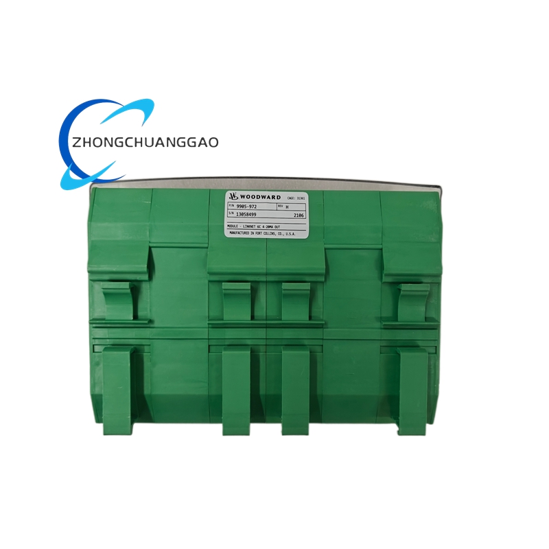
- Label area — laser-etched stainless steel plate on the enclosure face (model number, ratings, certifications, serial number); etching is permanent and resistant to chemicals, UV, and abrasion
- Cable entry points — M20 × 1.5 cable glands (4 × top, 2 × bottom, 2 × sides) with IP68 rated seals
Working Principle
- The controller draws self-power from the generator terminals via the 24 VDC system — no external power supply is required during normal operation
- Dual-Channel Barrier Interface:
- The controller connects to two independent intrinsically safe barriers (MTL, Bartec, or Pepperl+Fuchs) on the safe-area side
- Each barrier channel provides galvanic isolation and energy limitation between the safe-area controller and the hazardous-area field instruments
- The barrier limits voltage to Uo ≤ 28 VDC and current to Io ≤ 100 mA per channel (for standard IS) or Io ≤ 10 A per channel (for high-output IS barrier variants)
- The barrier ensures that even under fault conditions, the energy delivered to the hazardous area remains below the minimum ignition energy (MIE) of the surrounding explosive atmosphere
- Speed Control Loop (Governor):
- The magnetic pickup (MPU) mounted on the engine flywheel generates an AC voltage proportional to engine speed
- The controller converts the MPU signal to a digital speed value via an internal frequency-to-voltage converter
- The microprocessor compares the actual speed to the user-defined setpoint (isochronous or droop mode)
- The error signal is processed by a digital PID control algorithm with adjustable gain, integral, and derivative terms
- The PID output drives the governor actuator output (0–10 VDC or 4–20 mA), which controls the fuel valve actuator on the engine
- The fuel valve adjusts fuel flow to maintain the set speed regardless of load changes
- Voltage Control Loop (AVR):
- The 3-phase voltage sensing circuit continuously measures the generator terminal voltage (L1, L2, L3) via the barrier interface
- The microprocessor computes the RMS voltage and compares it to the user-defined voltage setpoint
- The error signal is processed by a digital PID control algorithm with adjustable gain and bandwidth
- The PID output drives a high-output PWM exciter field driver, which controls the DC current supplied to the brushless exciter field winding (up to 10 A DC per channel)
- The exciter field current adjusts the exciter stator output, which controls the main generator field current via the rotating rectifier assembly
- This closed-loop system maintains constant terminal voltage under all load conditions
- Protection Logic:
- The microprocessor continuously monitors speed, voltage, frequency, current, barrier status, and I/O states
- If any parameter exceeds a configurable threshold (over-speed, under-speed, over-voltage, under-voltage, over-frequency, under-frequency, over-current, reverse power, short circuit, ground fault, engine crank timeout, over-temperature, low oil pressure, high exhaust temperature, barrier fault), the controller immediately reduces or cuts excitation and/or fuel
- The emergency stop input takes immediate priority over all other functions, shutting down fuel and excitation within 10 ms
- The barrier fault monitoring detects open-circuit, short-circuit, or degraded isolation on either barrier channel and triggers an alarm or shutdown
- Parallel Operation (Droop Mode):
- When multiple generators operate in parallel, each unit is set to the same droop percentage (typically 4% or 5%)
- The droop characteristic causes each generator to share load proportionally to its capacity without a central load-sharing controller
- The automatic paralleling function monitors voltage, frequency, and phase angle; when all synchronization conditions are met (voltage within ±5%, frequency within ±0.1 Hz, phase angle within ±10°), the controller sends a close command to the breaker
- Data Logging and Communication:
- The controller records operating parameters (speed, voltage, frequency, load, alarms, barrier status) at configurable intervals (1 second to 1 hour)
- Event log stores the last 500 alarm events with timestamps (expandable to 5,000 with SD card) for root-cause analysis
- Data is accessible via the LCD display, RS-485 Modbus RTU, CAN bus, EtherNet/IP, USB, or SD card
Advantages and Highlights
- Dual-channel IS barrier interface — two independent barrier channels for maximum redundancy; if one barrier fails, the other maintains safe operation
- High-output exciter driver (10 A DC per channel) — powers large brushless exciter field windings directly; eliminates external power amplifiers in hazardous areas
- Single-unit GAVR + protection integration — replaces governor, AVR, protection relay, and synchronizing relay in one compact unit; reduces panel space, wiring, and cost by up to 60%
- Digital precision — ±0.05% speed regulation and ±0.5% voltage regulation; superior to analog controllers (typically ±0.5% speed, ±3% voltage)
- Zero drift over time — microprocessor-based control eliminates component aging drift inherent in analog designs
- Self-powered operation — derives all operating power from generator terminals; no external power supply needed
- Wide engine compatibility — supports gas turbines, diesel engines, dual-fuel engines, and steam turbines from 100 kW to 10,000 kW
- Fast transient response — <50 ms speed recovery and <30 ms voltage recovery on 100% load steps
- Built-in Modbus RTU, CAN, and EtherNet/IP communication — seamless integration with SCADA, BMS, and remote monitoring systems
- 240 × 128 color LCD touchscreen — real-time visualization of all operating parameters, waveforms, and event logs without a laptop
- Comprehensive protection suite — adjustable over/under-speed, over/under-voltage, over/under-frequency, over-current, reverse power, short circuit, ground fault, engine crank timeout, over-temperature, low oil pressure, high exhaust temperature, barrier fault, and emergency stop
- Parallel operation ready — droop control and automatic paralleling enable stable load sharing without external load-sharing controllers
- Event logging (500 events) — stores alarm history with timestamps for preventive maintenance
- Password-protected configuration — three access levels (operator, technician, engineer) prevent unauthorized parameter changes
- Front-panel commissioning — all setpoints, gains, and protection thresholds adjustable via touchscreen keypad without a laptop
- PC-based configuration — Woodward TOOLBOX software enables full parameter tuning, data logging, and firmware updates via RS-485, CAN, Ethernet, or USB
- Long service life — MTBF >200,000 hours, no moving parts, no wear-out components
- Robust environmental rating — operates from -25°C to +70°C; IP65 front panel rated for outdoor and washdown installations
- ATEX Zone 1/2 and IECEx certified — approved for the most hazardous gas atmospheres including hydrogen and acetylene (T6 temperature class)
- SIL 2 capable — meets IEC 61508 functional safety requirements for safety instrumented systems
- Compact form factor — fits in tight spaces on DIN rails and in control cabinets despite the large display and dual-channel architecture
Applicable Industries
| Industry | Application |
|---|---|
| Power Generation (Utility) | Large gas turbine and diesel generator sets (1 MW to 10 MW) in power plants and combined-cycle facilities |
| Oil and Gas (Upstream) | Wellhead power generation, pipeline SCADA, gas compression stations, flare system monitoring in Zone 1/2 areas |
| Oil and Gas (Downstream) | Refinery process control, tank farm monitoring, loading rack instrumentation, catalytic cracker control in Zone 1/2 areas |
| Chemical Processing | Reactor temperature/pressure monitoring, solvent level detection, valve actuation in hazardous areas |
| Pharmaceutical Manufacturing | Solvent recovery monitoring, reactor control, cleanroom-adjacent hazardous area instrumentation |
| Petrochemical | Ethylene/propylene plant instrumentation, flare system monitoring, compressor control in Zone 1 areas |
| Mining | Methane gas detection, conveyor monitoring, ventilation control in underground hazardous areas (Zone 1) |
| Marine and Offshore | Gas detection on FPSO/FSO, cargo tank monitoring, engine room instrumentation, dynamic positioning gensets |
| LNG and Cryogenic | Liquefied natural gas plant monitoring, boil-off gas control, cryogenic valve actuation |
| Power Generation (Distributed) | Commercial and industrial cogeneration (CHP), data center backup power, hospital standby power |
| Telecommunications | Cell tower and central office backup generators in remote hazardous locations |
| Water and Wastewater | Hydrogen sulfide (H2S) gas detection, chlorine monitoring, sludge digester control in Zone 1 areas |
| Pulp and Paper | Turpentine vapor detection, kiln gas monitoring, dust collector control in hazardous areas |
| Food and Beverage | Alcohol vapor detection, solvent-based cleaning monitoring, dust explosion prevention in Zone 2 areas |
| Agriculture | Grain dust explosion prevention, biogas monitoring, silo level detection |
| Military / Defense | Field-deployed tactical power systems, military base gensets, naval vessel generators |
| Renewable Energy | Biogas, biomass, and waste-to-energy generator sets in hazardous environments |
Installation Requirements
| Requirement | Specification |
|---|---|
| Mounting | 35 mm standard DIN rail (EN 60715) or panel mount with 4 × M8 stainless steel screws |
| Ambient Temperature | -25°C to +70°C (-13°F to +158°F) |
| Relative Humidity | 5% to 95% non-condensing (IP65 front rated for wet conditions) |
| Altitude | Up to 3,000 m (10,000 ft) above sea level (derate above 1,000 m) |
| Vibration | <5 g RMS (10–500 Hz), per IEC 60068-2-6 |
| Shock | <50 g, 11 ms half-sine, per IEC 60068-2-27 |
| Enclosure IP Rating | IP65 (front panel), IP20 (rear terminals — install in NEMA 1 or higher enclosure) |
| Clearance | Minimum 100 mm above and below for ventilation; 50 mm on sides; 150 mm in front for display access |
| Cable Sizing (Exciter Output F+/F−) | Minimum 2.5 mm² (14 AWG) copper for up to 10 A continuous per channel |
| Cable Sizing (Voltage Sensing L1/L2/L3/N) | Minimum 1.5 mm² (16 AWG) copper, shielded twisted pair recommended |
| Cable Sizing (Governor Actuator Output) | Minimum 1.0 mm² (18 AWG) copper, shielded recommended |
| Cable Sizing (MPU Speed Input) | Minimum 0.5 mm² (22 AWG) shielded twisted pair |
| Cable Sizing (Digital Inputs DI1–DI12) | Minimum 0.75 mm² (20 AWG) copper |
| Cable Sizing (Barrier Channel Wiring) | Minimum 0.5 mm² (22 AWG) copper, PTFE-insulated for hazardous area side |
| Grounding | Chassis ground required; connect to generator frame ground bus with minimum 6 mm² (10 AWG) copper; IS ground must be dedicated and separate from power ground |
| IS Ground Connection | Dedicated IS ground bar required; do not share with power ground or signal ground |
| Torque on Terminal Screws | 0.8 Nm (7 in-lb) maximum; do not overtighten |
| Torque on Mounting Bolts | 3.0 Nm (27 in-lb) maximum |
| EMI Environment | Install away from high-current switching devices; maintain 150 mm separation from VFDs and soft starters |
| Cable Routing (Barrier Channels) | Separate IS cables from power cables by minimum 150 mm; use dedicated cable trays; IS cables must be in IS-rated conduit |
| RS-485 Wiring | Use shielded twisted-pair cable; terminate with 120 Ω resistor at each end of the bus; maximum bus length 1,200 m (4,000 ft) |
| CAN Bus Wiring | Use shielded twisted-pair cable; terminate with 120 Ω resistor at each end; maximum bus length 40 m (131 ft) at 1 Mbps, 250 m (820 ft) at 250 kbps |
| Ethernet Wiring | Use Cat5e or Cat6 shielded twisted-pair cable; maximum cable length 100 m (328 ft) |
| Fuse Protection (Safe Area) | Recommended: 1 A fast-blow fuse per barrier channel on safe-area input; 500 mA fuse per digital input circuit |
| Surge Protection (Safe Area) | Recommended: TVS diode array on all safe-area inputs; MOV on 24 VDC power input |
Usage Precautions
- Never connect the controller to a live generator without verifying all wiring against the wiring diagram — incorrect connections will destroy the controller and damage the generator
- Verify phase sequence before energizing the generator — reverse phase sequence will cause the governor to malfunction and may damage the engine fuel system
- Verify MPU polarity and signal level before startup — incorrect MPU wiring causes erratic speed control and overspeed conditions
- Do not exceed the rated exciter output current of 10 A DC per channel (20 A total) — overloading will destroy the PWM output driver
- Do not bypass the built-in surge protection devices on barrier channels — external transients from lightning or switching will damage internal circuitry and compromise intrinsic safety
- Allow 30 seconds warm-up time after initial power-on before expecting accurate speed or voltage regulation
- Do not adjust internal gain trimmers unless qualified — incorrect settings cause governor oscillation (hunting) or AVR instability
- Use shielded cable for all analog and digital I/O in electrically noisy environments (near VFDs, welders, or large motors) to prevent false readings
- Ensure proper ventilation — do not install in a sealed enclosure without airflow; overheating above 70°C causes thermal shutdown
- Perform annual inspection of all terminal connections for tightness, corrosion, and wire insulation integrity
- Do not operate the controller with the front cover removed — exposed terminals carry up to 300 VDC and 10 A
- When replacing the unit, match the model number exactly — 9905-972 is not interchangeable with 9905-971 without reconfiguration
- Log all fault events using the built-in event log or external SCADA for preventive maintenance
- Do not use the controller with generators exceeding 690 VAC line-to-line — this will destroy the voltage sensing input circuit
- For parallel operation, configure identical droop settings on all units — mismatched droop causes circulating currents, instability, and equipment damage
- Test the emergency stop input monthly — verify that E-stop shuts down fuel and excitation within 10 ms
- Do not connect the governor actuator output to a non-compatible fuel valve — verify actuator type (0–10 VDC or 4–20 mA) matches the valve specification
- Store spare units in a dry, temperature-controlled environment (0°C to 40°C, <70% RH) with anti-static packaging
- Update firmware via Woodward TOOLBOX software to the latest version for improved algorithms and bug fixes
- Do not modify the internal firmware — only Woodward-authorized personnel should perform firmware updates
- Protect the LCD display from direct sunlight and UV exposure — prolonged UV exposure degrades the display contrast over time
- Use the correct system voltage variant — 9905-972 is for 24 VDC systems only; do not connect to 12 VDC, 120 VAC, or 240 VAC systems
- Verify barrier compatibility before commissioning — ensure the connected IS barrier is rated for the same gas group (IIC) and temperature class (T6) as the controller
- Do not mix IS cables with non-IS cables in the same tray — this creates a risk of energy transfer to non-IS equipment and voids ATEX/IECEx certification
- Perform barrier isolation testing annually — verify isolation resistance exceeds 100 MΩ on each barrier channel
- Do not use the controller in explosive atmospheres without a certified IS barrier — the controller alone is not intrinsically safe; the barrier provides the safety function
- When using automatic paralleling, verify synchroscope input wiring — incorrect synchroscope wiring causes false synchronization and equipment damage
- Do not exceed the maximum cable capacitance of 200 nF per barrier channel — excessive capacitance degrades signal integrity and may cause instability
- Do not exceed the maximum cable inductance of 10 mH per barrier channel — excessive inductance limits signal bandwidth and may cause false readings
Software and Configuration Tools
| Tool | Function |
|---|---|
| Woodward TOOLBOX Software | PC-based configuration via RS-485, CAN, or Ethernet; adjust setpoints, gains, bandwidths, droop, alarm thresholds, protection limits, and log fault history |
| Woodward 9900 Configurator | Web-based setup utility for quick commissioning and parameter backup via Ethernet |
| Modbus RTU Register Map | Standard register map for third-party SCADA and BMS integration (function codes 03, 04, 06, 16, plus custom Woodward codes) |
| CANopen Device Profile | Standard CANopen DS301 profile for integration with CANopen-compatible SCADA systems |
| EtherNet/IP CIP Interface | Standard EtherNet/IP Common Industrial Protocol for integration with Rockwell, Siemens, and other EtherNet/IP SCADA platforms |
| Analog Output Scaling | Configurable 4–20 mA or 0–10 VDC proportional to speed, voltage, load, frequency, or power factor |
| Digital Input Mapping | User-configurable functions for DI1–DI12 (start, stop, E-stop, mode select, alarm reset, parallel command, etc.) |
| Relay Output Mapping | User-configurable functions for RO1–RO6 (alarm, pre-alarm, run, fault, synchroscope status, barrier fault, etc.) |
| Firmware Update Utility | Upload new firmware versions via RS-485, CAN, Ethernet, USB, or SD card using TOOLBOX software |
| SD Card Data Export | Export event logs, operating data, and configuration backups to SD card for offline analysis |
| USB Data Export | Export event logs and configuration via USB mass storage for offline analysis |
Key Parameters Summary (Bold Reference)
| Field | Value |
|---|---|
| Product Name | Woodward 9905-972 EasyGen Digital Governor + AVR Controller |
| Controller Type | Microprocessor-Based Governor + AVR (GAVR) with Dual-Channel IS Barrier Interface |
| Output Configuration | High-Output (HO) — up to 10 A DC continuous per channel (20 A total) |
| Number of Channels | 2 channels (dual-channel barrier interface) |
| System Voltage | 24 VDC nominal (18 VDC to 32 VDC operating range) |
| Engine Types | Gas turbine, diesel engine, dual-fuel (gas/diesel), steam turbine |
| Generator Range | 100 kW to 10,000 kW (134 HP to 13,400 HP) |
| Speed Sensing | Magnetic pickup (MPU), 5–30 VAC, 100 Hz to 10 kHz |
| Voltage Sensing | 3-phase, 120 VAC to 690 VAC (line-to-line), 45 Hz to 65 Hz |
| Speed Accuracy (Isochronous) | ±0.05% of setpoint (±1.8 RPM at 3,600 RPM) |
| Speed Accuracy (Droop) | ±0.1% of setpoint |
| Voltage Accuracy | ±0.5% of setpoint (typical), ±0.25% (optimal) |
| Exciter Output (HO) | Up to 10 A DC continuous per channel, up to 300 VDC maximum per channel |
| Governor Output | 0–10 VDC or 4–20 mA (proportional, configurable) |
| Speed Response | <50 ms for 100% load step |
| Voltage Response | <30 ms for 100% load step |
| Gas Group | IIA, IIB, IIC (T1 to T6) |
| Dust Group | IIIA, IIIB, IIIC (T85°C to T135°C) |
| Zone Rating (Gas) | Zone 1, Zone 2 |
| Zone Rating (Dust) | Zone 21, Zone 22 |
| Isolation Voltage (Barrier) | 1500 VAC RMS (50 Hz, 1 minute) |
| Display | 240 × 128 pixel color LCD touchscreen |
| Digital I/O | 12 inputs, 6 relay outputs, 2 analog outputs |
| Communication | RS-485 Modbus RTU, CAN, EtherNet/IP, USB, SD card |
| Event Log | 500 events with timestamps (expandable to 5,000 with SD card) |
| Operating Temperature | -25°C to +70°C |
| Enclosure Rating | IP65 (front), IP20 (rear) |
| Certifications | UL 508, CE, CSA, IEC 61000-6-2, IEC 61000-6-4, ISO 8528, ATEX Zone 1/2, IECEx, FM Class I Div 1 Gr A-D, CSA Class I Div 1 Gr A-D, TIIS, SIL 2 |
| Mounting | 35 mm DIN rail or panel mount |
| Weight | 2.8 kg (6.2 lbs) |
| Dimensions (Approx.) | 200 mm × 150 mm × 140 mm (H × W × D) |
| MTBF | >200,000 hours at 25°C ambient |
Reviews
There are no reviews yet.