Product Short Description
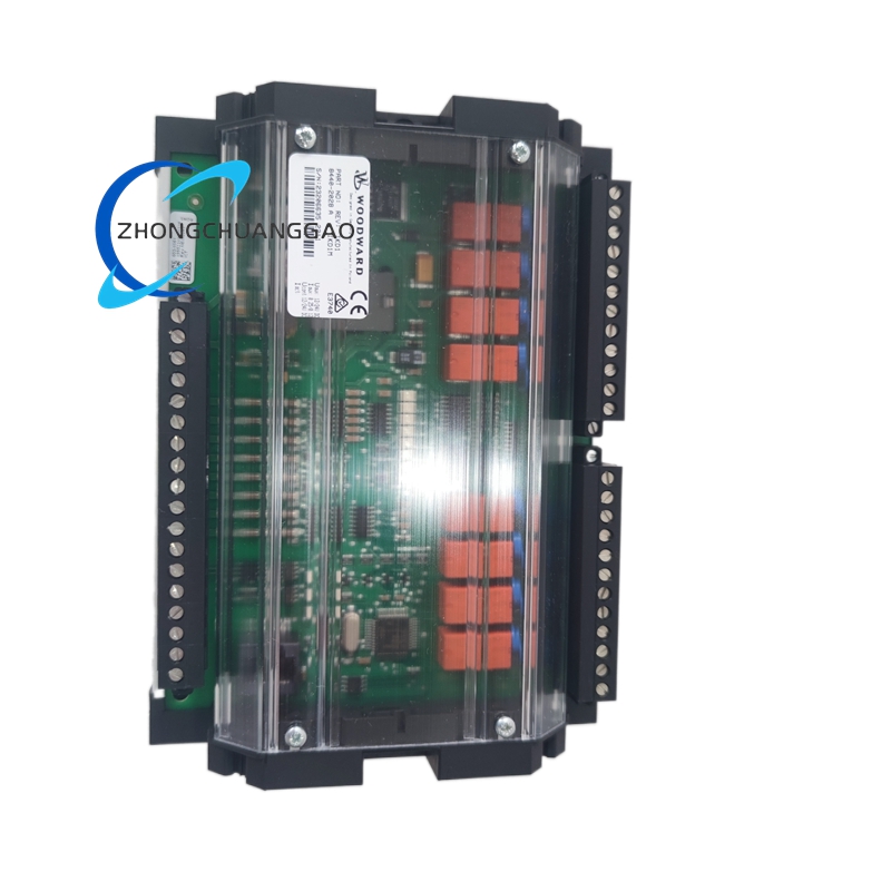
The Woodward 8440-2028 is a microprocessor-based digital generator set (genset) controller that integrates speed governing, automatic voltage regulation (AVR), engine protection, and generator protection into a single compact unit. It is part of the Woodward EasyGen 8440 Series, the latest-generation genset control platform that replaced the legacy EasyGen 3533 series. The 8440-2028 is configured for 24 VDC control systems and includes Modbus RTU communication for integration with supervisory control, SCADA, BMS, and remote monitoring platforms.
Description
Model Series
| Model | Series | System Voltage | Key Variant |
|---|---|---|---|
| 8440-2028 | EasyGen 8440 | 24 VDC | Modbus RTU, standard I/O |
| 8440-1028 | EasyGen 8440 | 12 VDC | Modbus RTU, standard I/O |
| 8440-3028 | EasyGen 8440 | 120 VAC | Modbus RTU, standard I/O |
| 8440-4028 | EasyGen 8440 | 240 VAC | Modbus RTU, standard I/O |
| 8440-2038 | EasyGen 8440 | 24 VDC | Modbus RTU + CAN bus |
| 8440-2048 | EasyGen 8440 | 24 VDC | Modbus RTU + EtherNet/IP |
| 8440-2018 | EasyGen 8440 | 24 VDC | Modbus RTU, reduced I/O |
| 8440-2058 | EasyGen 8440 | 24 VDC | Modbus RTU + USB + SD card |
| 8440-1018 | EasyGen 8440 | 12 VDC | Modbus RTU, reduced I/O |
| 8440-3018 | EasyGen 8440 | 120 VAC | Modbus RTU, reduced I/O |
| 8440-4018 | EasyGen 8440 | 240 VAC | Modbus RTU, reduced I/O |
| 8440-2022 | EasyGen 8440 | 24 VDC | Modbus RTU, dual-engine |
| 8440-2026 | EasyGen 8440 | 24 VDC | Modbus RTU, load share |
| 8440-2024 | EasyGen 8440 | 24 VDC | Modbus RTU, synchroscope |
| 8440-2020 | EasyGen 8440 | 24 VDC | Modbus RTU, base model |
| 8400-1000 | EasyGen 8400 | 12 VDC | Legacy analog governor/AVR (predecessor) |
| 8410-1000 | EasyGen 8410 | 12 VDC | Legacy digital governor/AVR (predecessor) |
Technical Specifications
| Parameter | Value |
|---|---|
| Controller Type | Microprocessor-Based Digital Genset Controller (Governor + AVR + Protection) |
| Engine Type Supported | Gas turbine, diesel engine, dual-fuel (gas/diesel) |
| Generator Size Range | 30 kW to 5,000 kW (40 HP to 6,700 HP) |
| System Voltage | 24 VDC (nominal), 18 VDC to 32 VDC operating range |
| Speed Sensing Input | Magnetic pickup (MPU), 5–30 VAC, 100 Hz to 10 kHz |
| Voltage Sensing Input | 3-phase, 120 VAC to 600 VAC (line-to-line), 45 Hz to 65 Hz |
| Speed Control Mode | Isochronous (0% droop) or Droop (1% to 10% selectable) |
| Speed Setpoint Range | 1,000 RPM to 1,800 RPM (adjustable via keypad or software) |
| Speed Regulation Accuracy | ±0.1% of setpoint (isochronous), ±0.25% (droop mode) |
| Voltage Setpoint Range | 90 VAC to 130 VAC (adjustable) |
| Voltage Regulation Accuracy | ±1% of setpoint (typical), ±0.5% (optimal) |
| Exciter Output Current | Up to 10 A DC continuous |
| Exciter Output Voltage | Up to 300 VDC maximum |
| Governor Actuator Output | 0–10 VDC or 4–20 mA (proportional) |
| Response Time (Speed) | <100 ms for 100% load step |
| Response Time (Voltage) | <50 ms for 100% load step |
| Operating Temperature | -20°C to +70°C (-4°F to +158°F) |
| Storage Temperature | -40°C to +85°C (-40°F to +185°F) |
| Power Supply | Self-powered from generator terminals (24 VDC system) |
| Communication Interface | RS-485 Modbus RTU (default), optional CAN, EtherNet/IP, USB |
| Analog Outputs | 2 × 4–20 mA or 0–10 VDC (configurable) |
| Digital Inputs | 8 × dry contact (NO/NC), 24 VDC |
| Digital Outputs (Relays) | 4 × programmable relay outputs (NO/NC), 250 VAC / 5 A |
| Display | 128 × 64 pixel color LCD with backlight |
| Mounting | 35 mm standard DIN rail (EN 60715) or panel mount |
| Dimensions (Approx.) | 160 mm × 120 mm × 130 mm (H × W × D) |
| Weight (Approx.) | 1.4 kg (3.1 lbs) |
| Certifications | UL 508, CE, CSA, IEC 61000-6-2, IEC 61000-6-4, ISO 8528, ATEX Zone 2 (with barrier) |
| Protection Rating | IP20 (enclosed installation required for outdoor use) |
| Event Log Capacity | 200 events with timestamps (expandable to 1,000 with SD card) |
| Firmware Update | Via USB, RS-485, or SD card |
Functional Features
- Integrated governor and AVR in one unit — eliminates separate controller hardware, wiring, and synchronization complexity
- Isochronous and droop speed control with user-selectable droop percentage (1% to 10%) for single-unit or parallel operation
- 3-phase voltage sensing with phase-loss detection, phase-sequence verification, and phase-rotation indication
- Magnetic pickup (MPU) speed input compatible with most engine-mounted pickups (5–30 VAC, 100 Hz to 10 kHz)
- Color LCD display — shows real-time speed, voltage, frequency, load, fuel level, and alarm status; supports multiple languages
- Adjustable voltage setpoint via front-panel keypad, remote digital command, or PC software
- Comprehensive protection suite: over-speed, under-speed, over-voltage, under-voltage, over-frequency, under-frequency, over-current, reverse power, short circuit, ground fault, engine crank timeout, and emergency stop
- Governor fuel limit control with adjustable high-fuel-limit and low-fuel-limit settings
- Soft-start function for controlled engine startup and voltage buildup
- Load-share (droop) mode for stable parallel operation of multiple generators
- Remote sensing capability for compensating voltage drop across long cable runs
- RS-485 Modbus RTU communication for SCADA, BMS, and remote monitoring integration
- Two configurable analog outputs (4–20 mA or 0–10 VDC) for external monitoring of speed, voltage, load, or frequency
- Eight digital inputs for remote start/stop, emergency stop, mode selection, and alarm signals
- Four programmable relay outputs for alarm, pre-alarm, run status, and fault indication
- Event logging stores the last 200 alarm events with timestamps (expandable to 1,000 with SD card option) for root-cause analysis
- Adjustable governor gain, speed loop bandwidth, and voltage loop bandwidth for optimization to specific engine/generator combinations
- Engine cranking output — provides a timed cranking signal to the engine starter during startup sequence
- Pre-lubrication timer — delay between start command and fuel admission for engine oil pressure buildup
- Emergency stop (E-stop) input — hardwired input that immediately shuts down fuel and excitation within 10 ms
- Adjustable acceleration/deceleration ramp rates for smooth speed transitions
- Built-in data logger — records operating parameters at configurable intervals for preventive maintenance
- Password-protected configuration — prevents unauthorized parameter changes
Performance Parameters
| Parameter | Specification |
|---|---|
| Speed Regulation (Isochronous) | ±0.1% of setpoint (±1.8 RPM at 1,800 RPM) |
| Speed Regulation (Droop Mode) | ±0.25% of setpoint |
| Voltage Regulation (Steady-State) | ±1% of nominal (95 VAC to 105 VAC at 100 VAC setpoint) |
| Transient Response (Speed, 100% Load Step) | <100 ms recovery to ±0.5% |
| Transient Response (Voltage, 100% Load Step) | <50 ms recovery to ±2% |
| Frequency Response | 45 Hz to 65 Hz (maintains regulation across full range) |
| Temperature Drift (Speed) | <0.01% per °C (after warm-up) |
| Temperature Drift (Voltage) | <0.01% per °C (after warm-up) |
| Line Voltage Effect (AVR) | <0.1% output change per 10% input voltage variation |
| Load Effect (Reactive, AVR) | <0.5% voltage change from no-load to full-load at 0.8 PF lagging |
| Governor Deadband | Adjustable: 0.01% to 0.5% of setpoint (default 0.05%) |
| Governor Speed Loop Bandwidth | Adjustable: 0.5 Hz to 20 Hz (typical setting: 2–5 Hz) |
| AVR Voltage Loop Bandwidth | Adjustable: 1 Hz to 50 Hz (typical setting: 5–10 Hz) |
| MTBF (Mean Time Between Failures) | >150,000 hours (at 25°C ambient) |
| Insulation Resistance | >100 MΩ at 500 VDC (between terminals and chassis) |
| Dielectric Strength | 2000 VAC RMS for 1 minute (input to chassis) |
| Harmonic Distortion (Exciter Output) | <2% THD at full load |
| EMC Emissions | IEC 61000-6-4 (Industrial Environment) |
| EMC Immunity | IEC 61000-6-2 (Industrial Environment) |
| Display Refresh Rate | 2 Hz (updates every 500 ms) |
| Event Log Timestamp Resolution | 1 second |
| Communication Baud Rate | 9600, 19200, 38400, 57600, 115200 bps (configurable) |
| Modbus Function Codes | 03, 04, 06, 16 (standard) |
Material Composition
| Component | Material |
|---|---|
| Enclosure / Housing | Flame-retardant polycarbonate (UL 94 V-0 rated), matte black finish |
| PCB (Printed Circuit Board) | FR-4 glass epoxy, conformal coated with acrylic coating |
| Terminal Blocks | Phosphor bronze, tin-plated, screw-clamp type, rated 10 A |
| Connector Pins (RS-485, I/O) | Gold-plated brass |
| Mounting Bracket / DIN Rail Clip | Galvanized steel, powder-coated |
| LED Indicators | High-brightness epoxy-encapsulated LEDs (red, green, yellow, amber) |
| Internal Wiring | Tinned copper, 18 AWG minimum, silicone-insulated, 200°C rated |
| Heat Sink (Internal) | Extruded aluminum, anodized black |
| Gaskets / Seals (Front Panel) | Silicone rubber (VMQ), 70 Shore A hardness, IP20 rated |
| Relay Contacts (Internal) | Silver-cadmium oxide (AgCdO), 250 VAC / 5 A |
| Fuses (Internal, if equipped) | Glass tube, 500 mA, 250 VAC, fast-blow |
| Surge Protection Devices | TVS diodes and metal-oxide varistors (MOVs) on all external I/O |
| LCD Display Cover | Polycarbonate, anti-glare coated, scratch-resistant |
| Keypad Membrane | Silicone rubber, 4 × 4 button matrix, IP65 rated (front panel) |
| Internal Fasteners | Stainless steel 304 (AISI 304), Torx head |
Structural Features
- Compact DIN-rail mountable module designed for installation inside generator control panels or switchgear cabinets
- Front panel with color LCD display (128 × 64 pixels) — shows real-time speed, voltage, frequency, load percentage, fuel level, and alarm status
- Front-panel silicone keypad — 4 × 4 button matrix for navigating menus, adjusting setpoints, and viewing alarms; all buttons are sealed behind the IP65 membrane
- LED indicators on front panel: Power (green), Run (green), Fault (red), Alarm (yellow), Emergency Stop (red flashing)
- Rear terminal block array with clearly labeled connections for:
- Speed input (MPU+ / MPU−)
- Voltage sensing (L1, L2, L3, N)
- Exciter field output (F+, F−)
- Governor actuator output (0–10 VDC or 4–20 mA)
- Remote sense (RS+, RS−)
- Analog outputs (AO1, AO2)
- Digital inputs (DI1–DI8, common)
- Relay outputs (RO1–RO4, NO/NC/common)
- RS-485 communication (A, B, GND)
- Emergency stop (E-stop, NO/NC)
- Crank output (CRANK+, CRANK−)
- Auxiliary power (if external supply used)
- SD card slot (on 8440-2058 variant)
- USB port (on 8440-2058 variant)
- Adjustable gain and stability trimmers accessible via front panel (under hinged cover)
- Ventilation slots on top and bottom for natural convection cooling (no internal fan)
- EMC shielding via metal enclosure interior coating and filtered I/O connections
- Hinged front cover with tamper-resistant screws — protects terminals and keypad from dust and accidental contact
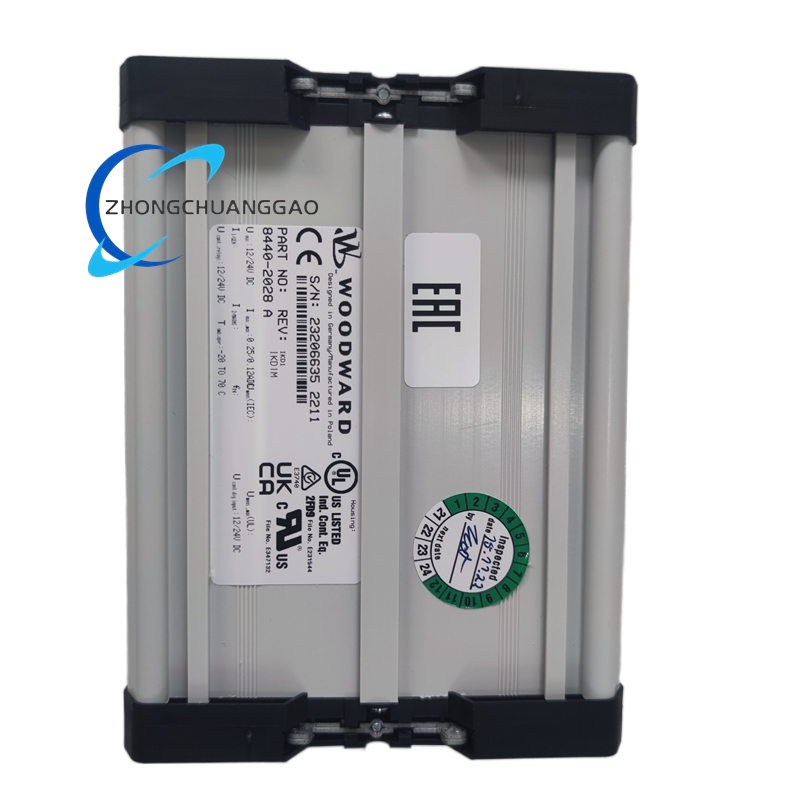
- Label area — laser-etched identification on the enclosure face (model number, ratings, certifications); etching is permanent and resistant to chemicals and abrasion
- DIN rail clip — spring-loaded 35 mm DIN rail mounting clip with captive screws
Working Principle
- The controller draws self-power from the generator terminals — no external power supply is required during normal operation
- Speed Control Loop (Governor):
- The magnetic pickup (MPU) mounted on the engine flywheel generates an AC voltage proportional to engine speed
- The controller converts the MPU signal to a digital speed value via an internal frequency-to-voltage converter
- The microprocessor compares the actual speed to the user-defined setpoint
- The error signal is processed by a digital PID control algorithm with adjustable gain and bandwidth
- The PID output drives the governor actuator output (0–10 VDC or 4–20 mA), which controls the fuel valve actuator on the engine
- The fuel valve adjusts fuel flow to maintain the set speed regardless of load changes
- Voltage Control Loop (AVR):
- The 3-phase voltage sensing circuit continuously measures the generator terminal voltage (L1, L2, L3)
- The microprocessor computes the RMS voltage and compares it to the user-defined voltage setpoint
- The error signal is processed by a digital PID control algorithm
- The PID output drives a PWM exciter field driver, which controls the DC current supplied to the brushless exciter field winding
- The exciter field current adjusts the exciter stator output, which controls the main generator field current via the rotating rectifier assembly
- This closed-loop system maintains constant terminal voltage under all load conditions
- Protection Logic:
- The microprocessor continuously monitors speed, voltage, frequency, current, and I/O states
- If any parameter exceeds a configurable threshold (over-speed, under-speed, over-voltage, under-voltage, phase loss, reverse power, ground fault), the controller immediately reduces or cuts excitation and/or fuel
- The emergency stop input takes immediate priority over all other functions, shutting down fuel and excitation within 10 ms
- Parallel Operation (Droop Mode):
- When multiple generators operate in parallel, each unit is set to the same droop percentage (typically 4% or 5%)
- The droop characteristic causes each generator to share load proportionally to its capacity without a central load-sharing controller
- The RS-485 Modbus RTU interface enables remote monitoring and control of each unit from a central SCADA or BMS
- Data Logging:
- The controller records operating parameters (speed, voltage, frequency, load, alarms) at configurable intervals (1 second to 1 hour)
- Event logs store the last 200 alarm events with timestamps for root-cause analysis
- Data is accessible via the LCD display, RS-485 Modbus RTU, or SD card (on 8440-2058 variant)
Advantages and Highlights
- Single-unit GAVR + protection integration — replaces governor, AVR, and protection relay in one compact unit, reducing cost, wiring, and panel space by up to 50%
- Digital precision — ±0.1% speed regulation and ±1% voltage regulation, superior to analog controllers (typically ±0.5% speed, ±3% voltage)
- Zero drift over time — microprocessor-based control eliminates component aging drift inherent in analog designs
- Self-powered operation — derives all operating power from generator terminals; no external power supply needed
- Wide engine compatibility — supports gas turbines, diesel engines, and dual-fuel engines from 30 kW to 5,000 kW
- Fast transient response — <100 ms speed recovery and <50 ms voltage recovery on 100% load steps
- Built-in Modbus RTU communication — seamless integration with SCADA, BMS, and remote monitoring systems
- Color LCD display — real-time visualization of all operating parameters without a laptop
- Configurable protection suite — adjustable over/under-speed, over/under-voltage, over/under-frequency, reverse power, ground fault, and emergency stop
- Parallel operation ready — droop control enables stable load sharing without external load-sharing controllers
- Event logging (200 events) — stores alarm history with timestamps for preventive maintenance
- Password-protected configuration — prevents unauthorized parameter changes
- Front-panel commissioning — all setpoints and gains adjustable via keypad without a laptop
- PC-based configuration — Woodward TOOLBOX software enables full parameter tuning, data logging, and firmware updates via RS-485 or USB
- Long service life — MTBF >150,000 hours, no moving parts, no wear-out components
- Robust environmental rating — operates from -20°C to +70°C, suitable for harsh industrial environments
- Compact form factor — fits in tight spaces on DIN rails and in control cabinets
Applicable Industries
| Industry | Application |
|---|---|
| Power Generation | Standby, prime, and continuous gas turbine and diesel generator sets |
| Oil and Gas | Remote well-site power, offshore platform gensets, gas compression stations |
| Mining | Underground and surface mine backup and prime power systems |
| Marine | Shipboard auxiliary generators, harbor power units, offshore support vessels |
| Data Centers | Emergency backup generator speed and voltage control |
| Hospitals | Critical care facility standby power with automatic transfer |
| Telecommunications | Cell tower and central office backup generators |
| Manufacturing | Factory cogeneration (CHP), process backup power |
| Commercial Buildings | Emergency standby generators for HVAC, lighting, elevators |
| Military / Defense | Field-deployed tactical power systems, military bases |
| Renewable Energy | Biogas, biomass, and waste-to-energy generator sets |
| Industrial Plants | Process backup power, black-start capable systems |
| Pipeline and Utilities | Remote pumping station and compressor station power |
| Events and Entertainment | Mobile generator sets for concerts, festivals, and film production |
| Agriculture | Irrigation pump and grain dryer generator sets |
| Water and Wastewater | Pump station and treatment plant backup power |
Installation Requirements
| Requirement | Specification |
|---|---|
| Mounting | 35 mm standard DIN rail (EN 60715) or panel mount with 4 × M4 screws |
| Ambient Temperature | -20°C to +70°C (-4°F to +158°F) |
| Relative Humidity | 5% to 95% non-condensing |
| Altitude | Up to 3,000 m (10,000 ft) above sea level (derate above 1,000 m) |
| Vibration | <5 g RMS (10–500 Hz), per IEC 60068-2-6 |
| Enclosure IP Rating | IP20 minimum (install in NEMA 1 or higher enclosure for outdoor use) |
| Clearance | Minimum 50 mm above and below for ventilation; 25 mm on sides |
| Cable Sizing (Exciter Output F+/F−) | Minimum 2.5 mm² (14 AWG) copper for up to 10 A continuous |
| Cable Sizing (Voltage Sensing L1/L2/L3/N) | Minimum 1.5 mm² (16 AWG) copper, shielded twisted pair recommended |
| Cable Sizing (Governor Actuator Output) | Minimum 1.0 mm² (18 AWG) copper, shielded recommended |
| Cable Sizing (MPU Speed Input) | Minimum 0.5 mm² (22 AWG) shielded twisted pair |
| Cable Sizing (Digital Inputs DI1–DI8) | Minimum 0.75 mm² (20 AWG) copper |
| Grounding | Chassis ground required; connect to generator frame ground bus with minimum 6 mm² (10 AWG) copper |
| Torque on Terminal Screws | 0.8 Nm (7 in-lb) maximum; do not overtighten |
| EMI Environment | Install away from high-current switching devices; maintain 100 mm separation from VFDs and soft starters |
| RS-485 Wiring | Use shielded twisted-pair cable; terminate with 120 Ω resistor at each end of the bus; maximum bus length 1,200 m (4,000 ft) |
| Power Wiring | Use dedicated conduit for generator voltage sensing and exciter output; separate from control wiring by minimum 100 mm |
| Fuse Protection (Safe Area) | Recommended: 500 mA fast-blow fuse per channel on safe-area input |
Usage Precautions
- Never connect the controller to a live generator without verifying all wiring against the wiring diagram — incorrect connections will destroy the controller and damage the generator
- Verify phase sequence before energizing the generator — reverse phase sequence will cause the governor to malfunction and may damage the engine fuel system
- Verify MPU polarity and signal level before startup — incorrect MPU wiring causes erratic speed control and overspeed conditions
- Do not exceed the rated exciter output current of 10 A DC — overloading will destroy the PWM output driver
- Do not bypass the built-in surge protection devices — external transients from lightning or switching will damage internal circuitry
- Allow 30 seconds warm-up time after initial power-on before expecting accurate speed or voltage regulation
- Do not adjust internal gain trimmers unless qualified — incorrect settings cause governor oscillation (hunting) or AVR instability
- Use shielded cable for all analog and digital I/O in electrically noisy environments (near VFDs, welders, or large motors) to prevent false readings
- Ensure proper ventilation — do not install in a sealed enclosure without airflow; overheating above 70°C causes thermal shutdown
- Perform annual inspection of all terminal connections for tightness, corrosion, and wire insulation integrity
- Do not operate the controller with the front cover removed — exposed terminals carry up to 300 VDC and 10 A
- When replacing the unit, match the model number exactly — 8440-2028 is not interchangeable with 8440-1028 without reconfiguration
- Log all fault events using the built-in event log or external SCADA for preventive maintenance
- Do not use the controller with generators exceeding 600 VAC line-to-line — this will destroy the voltage sensing input circuit
- For parallel operation, configure identical droop settings on all units — mismatched droop causes circulating currents, instability, and equipment damage
- Test the emergency stop input monthly — verify that E-stop shuts down fuel and excitation within 10 ms
- Do not connect the governor actuator output to a non-compatible fuel valve — verify actuator type (0–10 VDC or 4–20 mA) matches the valve specification
- Store spare units in a dry, temperature-controlled environment (0°C to 40°C, <70% RH) with anti-static packaging
- Update firmware via Woodward TOOLBOX software to the latest version for improved algorithms and bug fixes
- Do not modify the internal firmware — only Woodward-authorized personnel should perform firmware updates
- Protect the LCD display from direct sunlight — prolonged UV exposure degrades the display contrast over time
- Use the correct system voltage variant — 8440-2028 is for 24 VDC systems only; do not connect to 12 VDC or 120 VAC systems
Software and Configuration Tools
| Tool | Function |
|---|---|
| Woodward TOOLBOX Software | PC-based configuration via RS-485; adjust setpoints, gains, bandwidths, droop, alarm thresholds, and log fault history |
| Woodward 8440 Configurator | Web-based setup utility for quick commissioning and parameter backup |
| Modbus RTU Register Map | Standard register map for third-party SCADA and BMS integration |
| Analog Output Scaling | Configurable 4–20 mA or 0–10 VDC proportional to speed, voltage, load, or frequency |
| Digital Input Mapping | User-configurable functions for DI1–DI8 (start, stop, E-stop, mode select, etc.) |
| Relay Output Mapping | User-configurable functions for RO1–RO4 (alarm, pre-alarm, run, fault, etc.) |
| Firmware Update Utility | Upload new firmware versions via RS-485 or USB using TOOLBOX software |
| SD Card Data Export (8440-2058) | Export event logs and operating data to SD card for offline analysis |
Key Parameters Summary (Bold Reference)
| Field | Value |
|---|---|
| Product Name | Woodward 8440-2028 EasyGen Digital Genset Controller |
| Controller Type | Microprocessor-Based Governor + AVR + Protection |
| System Voltage | 24 VDC (18–32 VDC range) |
| Engine Types | Gas turbine, diesel, dual-fuel (gas/diesel) |
| Generator Range | 30 kW to 5,000 kW (40 HP to 6,700 HP) |
| Speed Sensing | Magnetic pickup (MPU), 5–30 VAC, 100 Hz–10 kHz |
| Voltage Sensing | 3-phase, 120–600 VAC, 45–65 Hz |
| Speed Accuracy | ±0.1% (isochronous), ±0.25% (droop) |
| Voltage Accuracy | ±1% of setpoint |
| Exciter Output | 0–10 A DC, up to 300 VDC |
| Governor Output | 0–10 VDC or 4–20 mA (proportional) |
| Speed Response | <100 ms (100% load step) |
| Voltage Response | <50 ms (100% load step) |
| Operating Temp | -20°C to +70°C |
| Communication | RS-485 Modbus RTU (default) |
| Digital I/O | 8 inputs, 4 relay outputs, 2 analog outputs |
| Display | 128 × 64 color LCD |
| Event Log | 200 events with timestamps (1,000 with SD card) |
| Mounting | 35 mm DIN rail or panel mount |
| MTBF | >150,000 hours at 25°C |
| Certifications | UL 508, CE, CSA, IEC 61000-6-2, IEC 61000-6-4, ISO 8528, ATEX Zone 2 (with barrier) |
| Weight | 1.4 kg (3.1 lbs) |
| Dimensions (Approx.) | 160 mm × 120 mm × 130 mm |
Reviews
There are no reviews yet.