Product Short Description
Product Overview
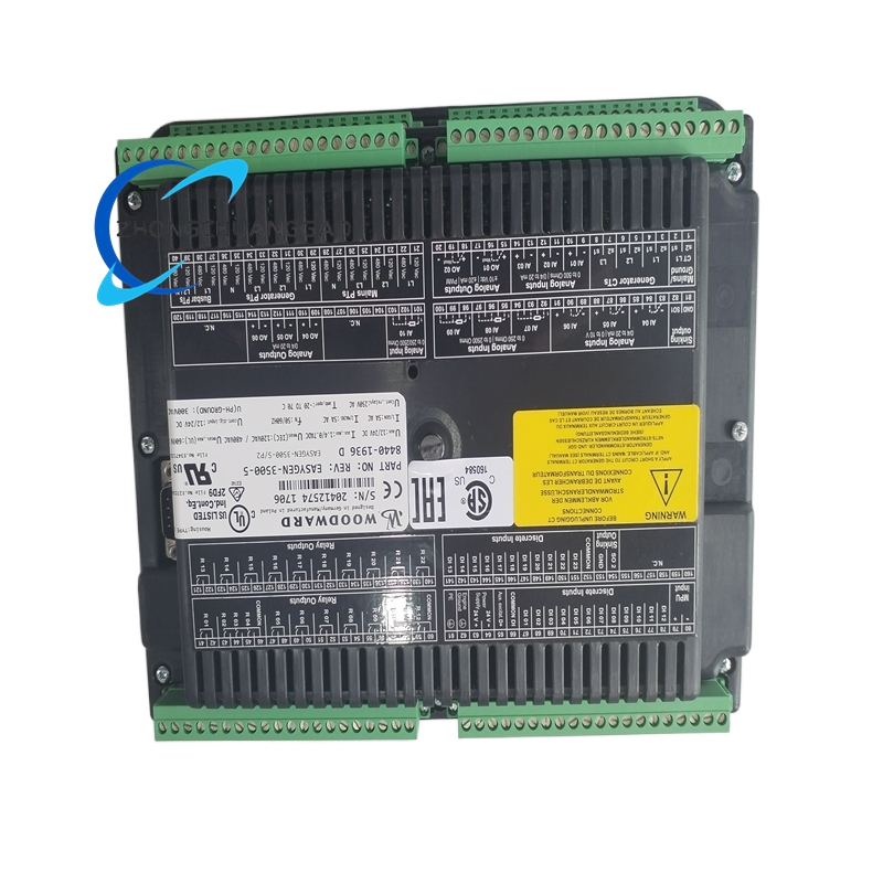
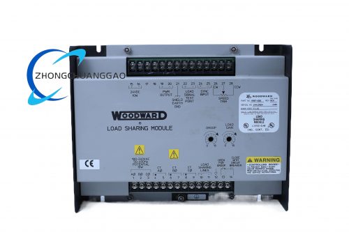
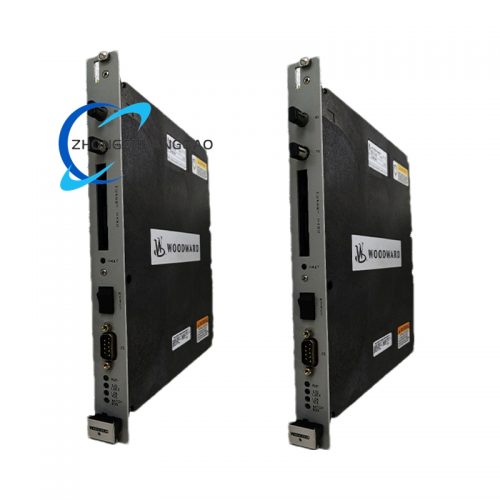
The Woodward 8440-1936 is a microprocessor-based load sharing and power management controller designed for parallel operation of multiple diesel or gas engine generator sets. It controls real power (kW) and reactive power (kVAR) sharing between generators, manages start/stop sequencing, and provides automatic bus tie breaker control. The unit replaces legacy electro-mechanical load sharing relays with a fully digital control platform and interfaces with Woodward EasYgen, 505E, and compatible engine controllers via CAN bus or analog signals.
Description
Product Category
Load Sharing Controller / Power Management System / Generator Synchronization Controller
Key Functions
- Real Power (kW) Load Sharing — Distributes active load equally among all parallel generators using droop control
- Reactive Power (kVAR) Load Sharing — Distributes reactive load equally using cross-current compensation
- Droop Control — Programmable droop from 0% to 10% for both kW and kVAR sharing
- Isochronous Operation — One generator operates in isochronous mode (0% droop) while others operate in droop mode
- Generator Start/Stop Sequencing — Automatic start and stop of standby generators based on load demand
- Bus Tie Breaker Control — Automatic open/close of bus tie breaker based on generator status and load conditions
- Under-Frequency Protection — Sheds non-essential loads when system frequency drops below threshold
- Over-Frequency Protection — Trips generators when system frequency exceeds threshold
- Reverse Power Protection — Detects and alarms on reverse power flow (motoring condition)
- Phase Sequence Monitoring — Detects incorrect phase sequence before allowing generator to close breaker
- Voltage Matching — Monitors and matches generator voltage to bus voltage before synchronization
- Frequency Matching — Monitors and matches generator frequency to bus frequency before synchronization
- Load Demand Control — Accepts a 4–20 mA or 0–10 VDC signal representing total load demand
- Remote Monitoring — Full status and diagnostic data available via CAN bus, Modbus RTU, or discrete I/O
Technical Specifications
| Parameter | Value |
|---|---|
| Supply Voltage | 24 VDC nominal (range: 18 VDC to 32 VDC) |
| Power Consumption | Less than 10 W typical |
| Operating Temperature | -40°C to +85°C (-40°F to +185°F) |
| Storage Temperature | -55°C to +125°C (-67°F to +257°F) |
| Humidity Rating | 5% to 95% non-condensing |
| Vibration Rating | IEC 60068-2-6 compliant |
| Altitude Rating | Up to 10,000 ft (3,048 m) without derating |
| EMC Compliance | IEC 61000-6-2 (Industrial Environment) |
| Enclosure Protection | IP54 (front panel) |
| Weight | Approximately 1.2 kg (2.6 lbs) |
| Dimensions (L x W x H) | Approximately 210 mm x 150 mm x 85 mm |
| Number of Generator Channels | Up to 4 generators (8440-1936 supports 4-channel configuration) |
| Communication | CAN bus, Modbus RTU, discrete I/O, analog I/O |
Input Specifications
| Input Type | Quantity | Specification |
|---|---|---|
| Analog Inputs (Load Demand) | 2 | 4 mA to 20 mA or 0 VDC to 10 VDC |
| Analog Inputs (Generator kW) | 4 | 4 mA to 20 mA (from CT or transducer) |
| Analog Inputs (Generator kVAR) | 4 | 4 mA to 20 mA (from CT or transducer) |
| Analog Inputs (Bus Voltage) | 1 | 0 VDC to 10 VDC or 4 mA to 20 mA |
| Analog Inputs (Bus Frequency) | 1 | 45 Hz to 65 Hz, 0.5 VDC to 4.5 VDC |
| Discrete Inputs | 12 | Dry contact (start/stop, alarm, status, mode select) |
| Discrete Outputs | 8 | Relay contacts (alarm, trip, breaker control, status) |
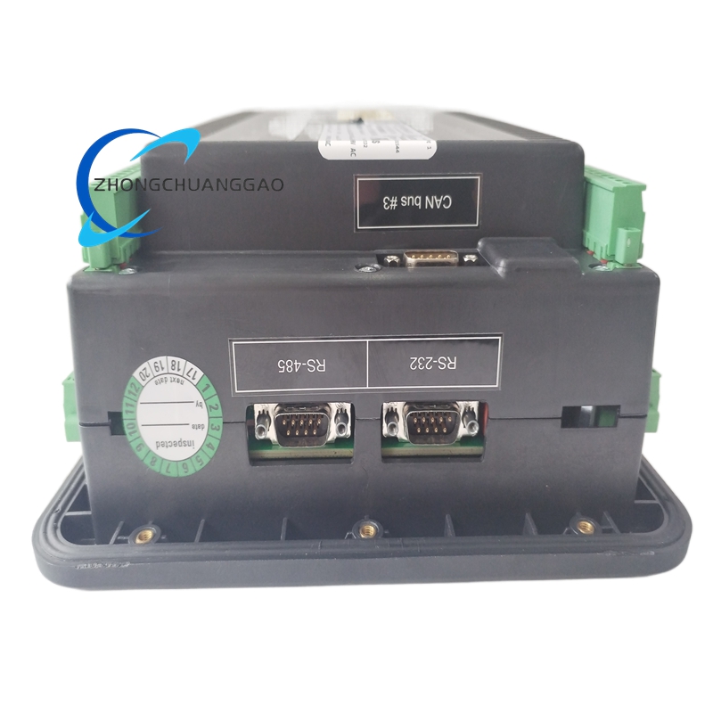
| CAN Bus | 1 | Woodward CAN 2.0B, 500 kbps |
| Serial Port | 1 | RS-485, Modbus RTU |
Output Specifications
| Output Type | Quantity | Specification |
|---|---|---|
| Relay Outputs (Breaker Control) | 4 | 5 A at 250 VAC / 30 VDC (changeover contact) |
| Relay Outputs (Alarm/Trip) | 4 | 5 A at 250 VAC / 30 VDC (changeover contact) |
| Analog Outputs (Load Share Reference) | 2 | 4 mA to 20 mA (to engine governors) |
| Analog Outputs (Status) | 2 | 4 mA to 20 mA (kW, kVAR, frequency, voltage) |
Protection Features
- Over-Frequency Trip — Configurable trip point 47 Hz to 63 Hz, adjustable delay 0 to 30 seconds
- Under-Frequency Trip — Configurable trip point 45 Hz to 59 Hz, adjustable delay 0 to 30 seconds
- Over-Frequency Alarm — Alarm activates 0.5 Hz below trip point
- Under-Frequency Alarm — Alarm activates 0.5 Hz above trip point
- Reverse Power Trip — Configurable trip point 1% to 15% of rated kW, delay 0 to 10 seconds
- Reverse Power Alarm — Alarm activates 50% of trip point
- Phase Failure Protection — Detects loss of any phase, trips generator within 200 ms
- Phase Sequence Protection — Blocks breaker close on incorrect phase sequence
- Voltage Mismatch Protection — Blocks breaker close if voltage difference exceeds 10%
- Frequency Mismatch Protection — Blocks breaker close if frequency difference exceeds 0.5 Hz
- CT Failure Detection — Detects open or short circuit on current transformer inputs
- Supply Voltage Monitor — Low alarm at <18 VDC, high alarm at >32 VDC
- CAN Bus Timeout — Drives outputs to safe state within 200 ms of bus loss
Droop Settings
| Mode | kW Droop | kVAR Droop | Application |
|---|---|---|---|
| Isochronous | 0% | 0% | Single generator or master in parallel set |
| Droop (Standard) | 4% to 5% | 4% to 5% | Equal load sharing among 2–4 generators |
| Programmable | 0% to 10% | 0% to 10% | Custom load sharing requirements |
Material Composition
| Component | Material |
|---|---|
| Housing | Die-cast aluminum alloy with powder-coat finish (RAL 7035 light gray) |
| Front Panel | Polycarbonate with UV-resistant coating and membrane keypad overlay |
| PCB | FR-4 fiberglass epoxy, conformally coated with silicone |
| Connectors | Phoenix Contact screw terminal blocks, tin-plated brass |
| Relay Contacts | Silver-cadmium oxide (AgCdO) for high-reliability switching |
| Mounting Bracket | Stainless steel 304 with vibration-damping rubber grommets |
| Gaskets/Seals | FKM (Viton) O-rings for IP54 sealing |
| LEDs | High-brightness LEDs, rated 100,000 hours |
Structural Features
- DIN rail mountable on 35 mm top-hat rail (EN 60715)
- Front-accessible terminal blocks for all wiring connections
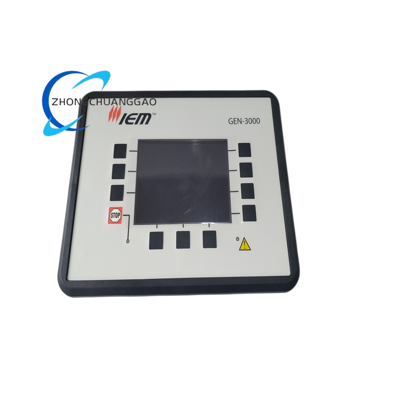
- Membrane keypad with 4-line backlit LCD display for local configuration
- 4 LED status indicators: Power (green), Run (green), Alarm (amber), Fault (red)
- Conformal-coated PCB for moisture and chemical resistance
- Integrated EMC filter on all analog and digital inputs
- DIP switches on PCB for mode selection and configuration
- DB-9 connector for CAN bus and RS-485 serial communication
Working Principle
The 8440-1936 receives real-time measurements from current transformers (CTs) and voltage transformers (VTs) connected to each generator and the common bus. The internal 32-bit microcontroller calculates the real power (kW) and reactive power (kVAR) for each generator using the measured voltage, current, and power factor. The controller compares each generator’s kW output to the total system kW demand and adjusts the droop reference signal sent to each engine’s governor via analog output (4–20 mA) or CAN bus. This ensures that each generator picks up its proportional share of the total load. For kVAR sharing, the controller measures the reactive current from each generator and adjusts the voltage regulator reference to equalize reactive load distribution. The synchronization function monitors voltage magnitude, frequency, and phase angle of each generator relative to the bus. When all synchronization conditions are met (voltage within 10%, frequency within 0.5 Hz, phase sequence correct, phase angle within tolerance), the controller sends a breaker-close command to the generator circuit breaker. The start/stop sequencer monitors total load demand and automatically starts standby generators when load exceeds a configurable threshold and stops them when load falls below a lower threshold.
Advantages and Highlights
- Fully Digital Architecture — Zero analog drift, no calibration degradation over time
- 4-Generator Support — Manages up to 4 generators in parallel with independent kW and kVAR control
- Dual Droop Control — Simultaneous kW and kVAR load sharing with programmable droop from 0% to 10%
- Automatic Synchronization — Voltage, frequency, phase sequence, and phase angle matching before breaker close
- Bus Tie Breaker Control — Automatic bus tie open/close based on generator status and load
- CAN Bus Integration — Native communication with EasYgen 3000/3500/4000 and EGC-4 controllers
- Comprehensive Protection — Over/under frequency, reverse power, phase failure, CT failure, voltage mismatch
- IP54 Rating — Suitable for harsh industrial and outdoor environments
- Long Service Life — MTBF exceeds 80,000 hours, no mechanical wear components
- Field Configurable — All parameters adjustable via front panel, Modbus RTU, or Woodward software
- Start/Stop Sequencing — Automatic generator management based on load demand
Applicable Industries
- Power Generation — Diesel and gas generator sets in parallel (standby, prime, continuous duty)
- Marine Propulsion — Main engine and generator load sharing on vessels
- Oil and Gas — Compressor driver generators, wellhead power units, FPSO power systems
- Mining — Diesel generator sets for underground and surface operations
- Data Centers — N+1 or 2N redundant generator configurations
- Hospitals — Critical power systems with automatic transfer and load sharing
- Industrial Co-Generation — CHP plants with multiple engine-generators
- Military/Defense — Mobile and stationary tactical power systems
- Telecommunications — Cell tower and central office backup power
Compatible Engine Controllers
| Controller | Communication |
|---|---|
| EasYgen 3000 / 3500 / 4000 | CAN bus (primary) |
| EGC-4 | CAN bus (primary) |
| 505E / 505D | Analog 4–20 mA (backup) |
| EASYgen-3200 | CAN bus |
| Woodward 9907 Actuators | Analog 4–20 mA or CAN bus |
Model Series Cross-Reference
| Model | Channels | Key Difference from 8440-1936 |
|---|---|---|
| 8440-1932 | 2 generators | 2-channel version, same features |
| 8440-1934 | 3 generators | 3-channel version, same features |
| 8440-1936 | 4 generators | Reference model — full 4-channel kW/kVAR sharing |
| 8440-1938 | 6 generators | 6-channel version, same features |
| 8440-1940 | 8 generators | 8-channel version, same features |
| 8440-1936R | 4 generators + Ring | Adds MRP ring protection for zero-downtime |
Certifications and Compliance
| Certification | Standard |
|---|---|
| CE Marking | EN 61010-1, EN 55032 Class A, EN 61000-6-2, EN 61000-6-4 |
| UL Listed | File E147353 (North America) |
| CSA Certified | File LR78161 (Canada) |
| DNV GL Type Approval | For marine installations |
| Lloyd’s Register | Approved for marine generator sets |
| ABS | Approved for marine use |
| RoHS Compliant | EU Directive 2011/65/EU |
| REACH Compliant | EU Regulation 1907/2006 |
| IEC 61000-6-2 | EMC emission and immunity for industrial environments |
| IEC 60068-2-6 | Vibration resistance |
| IEC 60529 | IP54 ingress protection |
Part Number Breakdown
| Segment | Meaning |
|---|---|
| 8440 | Product family — Load Share and Power Management Controller |
| 19 | Feature set — Full kW/kVAR sharing, 4-channel, bus tie control |
| 36 | Configuration code — 4-generator, CAN bus, Modbus RTU, IP54 |
Installation Requirements
- Mount on 35 mm DIN rail (EN 60715) or wall mount using supplied bracket
- Maintain minimum 50 mm clearance on all sides for ventilation
- Route CT and VT cables away from high-current power cables (minimum 200 mm separation)
- Use shielded twisted-pair cable for all analog signal wiring (minimum 24 AWG)
- Ground the chassis to the panel ground bus using minimum 10 AWG copper wire
- Supply voltage must be 24 VDC regulated with less than 5% ripple
- Torque all terminal connections to 1.5 Nm (13.3 in-lbs)
- Connect CT secondary leads directly to the 8440-1936 terminals — do not route through other devices
- Connect VT secondary leads directly to the 8440-1936 terminals
- Verify all breaker control relay outputs are wired to the correct generator breaker coils
- Install 120 Ω termination resistors at both ends of the CAN bus
Usage Precautions
- Do not exceed the maximum supply voltage of 32 VDC — permanent damage to internal components will occur
- Do not reverse the power supply polarity — internal fuse will open
- Do not operate the unit in environments exceeding +85°C ambient temperature
- Do not exceed the rated CT secondary current of 5 A — this will damage the input circuitry
- Do not open the CT secondary circuit while the primary is energized — this will generate dangerous high voltage
- Do not disconnect or reconnect CT or VT leads while the unit is powered — this will cause measurement errors and alarms
- Perform a no-load calibration check after initial installation
- Perform a functional test of all protection relays every 6 months
- Do not modify the firmware using unauthorized tools — this voids the warranty immediately
- The unit contains no user-serviceable components — contact Woodward for all repairs
- Replace the FKM (Viton) O-rings if the IP54 seal is compromised
- Verify CAN bus termination resistors (120 Ω) are installed at both ends of the bus at all times
- Store the unit in a dry environment with relative humidity below 85%
Warranty
- Standard Warranty: 24 months from date of shipment
- Extended Warranty: Available up to 60 months (Woodward Protect program)
- Warranty Exclusions: Damage caused by reverse polarity, overvoltage, CT open circuit, physical impact, unauthorized firmware modification, or operation outside specified environmental limits
Document Reference Numbers
| Document | Number |
|---|---|
| Installation Manual | 8440-IM-001 |
| Operator’s Manual | 8440-OM-001 |
| Configuration Guide | 8440-CG-001 |
| Wiring Diagram | 8440-WD-001 |
| CAN Bus Communication Guide | 8440-CB-001 |
| Diagnostic Procedures | 8440-DP-001 |
| Calibration Guide | 8440-CAL-001 |
| CT/VT Wiring Guide | 8440-CTVT-001 |
.jpg)
Reviews
There are no reviews yet.