Product Short Description
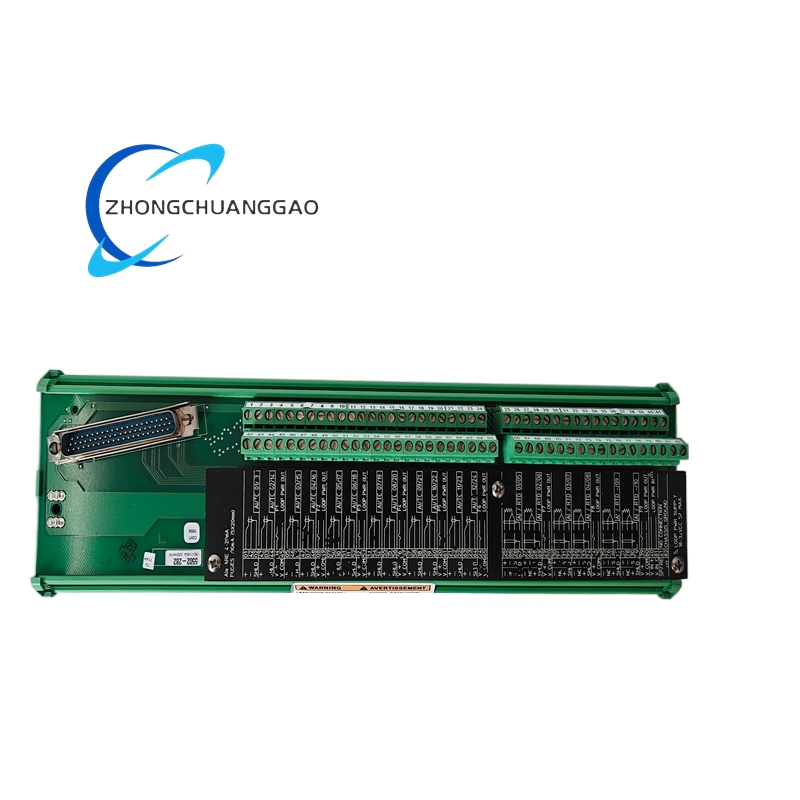
The Woodward 5503-282 is a digital electro-hydraulic servo actuator controller designed to drive Woodward 9907, 9903, and compatible electro-hydraulic servo actuators for precise turbine valve position control. It serves as the final control element interface between a digital governor (such as the Woodward 5437 Series) and the hydraulic actuator that positions the turbine main steam valve, control valve, or fuel valve.
Description
Technical Specifications
| Parameter | Specification |
|---|---|
| Model Number | 5503-282 |
| Series | 5503 Series |
| Controller Type | Digital Electro-Hydraulic Servo Actuator Controller |
| Output Channels | 2 independent servo drive channels (CH1, CH2) |
| Output Current per Channel | ±250 mA continuous (peak ±500 mA for 10 seconds) |
| Output Voltage per Channel | ±50 VDC maximum (compliance voltage) |
| Compatible Actuators | Woodward 9907, 9903, 9907A, 9903A, and equivalent EH servo actuators |
| Position Feedback Input | LVDT or RVDT, ±10 VAC or 4-20 mA (configurable per channel) |
| Position Feedback Resolution | 16-bit ADC, 0.0015% of full scale |
| Command Input Signal | 4-20 mA (2-wire) or ±50 mA (from governor) |
| Command Input Impedance | 250 Ohms (4-20 mA mode), 50 Ohms (±50 mA mode) |
| Valve Position Range | 0% to 100% stroke (configurable) |
| Position Control Accuracy | ±0.1% of full stroke (steady state) |
| Position Repeatability | ±0.05% of full stroke |
| Response Time (10% to 90% stroke) | < 150 ms (typical) |
| Communication Protocols | Modbus RTU (RS-485), Modbus TCP (Ethernet) |
| Power Supply | 24 VDC nominal, 18 VDC to 30 VDC operating range |
| Power Consumption | < 12 Watts (typical, both channels active) |
| Operating Temperature | -20°C to +70°C (-4°F to +158°F) |
| Storage Temperature | -40°C to +85°C (-40°F to +185°F) |
| Humidity Range | 5% to 95% non-condensing |
| Vibration Tolerance | 5g peak, 10 Hz to 200 Hz (per IEC 60068-2-6) |
| Shock Tolerance | 15g, 11 ms half-sine (per IEC 60068-2-27) |
| EMC Compliance | IEC 61000-6-2 (industrial), IEC 61000-6-4 (emission) |
| Dimensions (H × W × D) | Approximately 9.5 in × 7.0 in × 5.5 in (241 mm × 178 mm × 140 mm) |
| Weight | Approximately 4.5 lbs (2.0 kg) |
| Mounting | Panel-mount, DIN rail, or direct wall-mount with brackets |
| Certifications | CE Marked, ATEX Zone 2 (optional), UL/CSA listed (variant dependent) |
| SIL Rating | SIL 2 (per IEC 61508, SIL 3 achievable with redundant configuration) |
| Drop-in Replacement For | Woodward 505F actuator controller, Woodward 9907-010 analog servo driver |
Functional Features
- Dual independent servo drive channels (CH1 and CH2) — supports main valve plus control valve, or dual-actuator parallel operation
- High-current servo amplifier — delivers ±250 mA continuous to the actuator torque motor, sufficient for Woodward 9907 and 9903 series actuators up to 10,000 lbf thrust
- Integrated LVDT/RVDT signal conditioning — accepts ±10 VAC or 4-20 mA position feedback, provides automatic excitation for LVDT sensors
- Valve position PID control — onboard digital PID controller regulates valve position based on command signal and feedback, eliminates need for separate positioner
- Built-in servo amplifier — no external servo amplifier required, reduces wiring and installation complexity
- Position ramp generator — programmable valve opening and closing ramp rates for smooth startup and shutdown
- Anti-windup PID — prevents integral windup during actuator saturation, ensures fast recovery from large disturbances
- Current limiting — programmable per-channel current limit protects actuator torque motor from overcurrent damage
- Position deviation alarm — configurable alarm relay activates if valve position deviates from command by more than preset threshold
- Trip relay output — 1 Form C trip relay de-energizes turbine trip solenoid on position fault or communication loss
- Auxiliary relay outputs — 3 programmable Form C auxiliary relays for status indication, alarm, or interlock functions
- Analog output — 1 configurable 4-20 mA output for real-time valve position transmission to DCS/SCADA
- Event logging — onboard non-volatile memory stores up to 500 time-stamped events including position faults and trip history
- Self-diagnostics — continuous monitoring of servo current, position feedback signal quality, internal CPU health, and relay status
- Modbus RTU/TCP communication — receives valve position command from governor and transmits position feedback and status to DCS/SCADA
- Web-based configuration — full parameter programming via Woodward GMT (Governor Management Tool) software over Ethernet
- Redundant configuration support — dual power input terminals for redundant 24 VDC supplies in SIL 3 applications
Performance Parameters
| Parameter | Value |
|---|---|
| Servo Output Current (Continuous) | ±250 mA per channel |
| Servo Output Current (Peak, 10 sec) | ±500 mA per channel |
| Servo Output Compliance Voltage | ±50 VDC |
| Position Control Accuracy (Steady State) | ±0.1% of full stroke |
| Position Repeatability | ±0.05% of full stroke |
| Position Response Time (10% to 90%) | < 150 ms (typical) |
| Position Response Time (Full Stroke) | < 500 ms (typical) |
| LVDT Excitation Frequency | 2.5 kHz or 10 kHz (configurable) |
| LVDT Excitation Voltage | ±5 VAC or ±10 VAC (configurable) |
| Position Feedback Noise Rejection | > 60 dB common-mode rejection |
| Servo Amplifier Bandwidth | 0 Hz to 100 Hz (-3 dB) |
| Current Limit Accuracy | ±2% of setpoint |
| Communication Update Rate (Modbus) | 10 ms to 100 ms (configurable) |
| Warm-up Time to Operational | < 30 seconds from power-on |
| Maximum LVDT Input Frequency | 500 Hz (supports high-speed position feedback) |
| Minimum LVDT Input Signal | 0.5 VAC (detects open circuit below 0.5 VAC) |
| Maximum LVDT Input Signal | 15 VAC (detects overrange above 15 VAC) |
| Trip Relay Response Time | < 50 ms from fault detection to relay activation |
| Analog Output Resolution | 16-bit DAC, 0.0015% full scale |
| Analog Output Update Rate | 10 ms (typical) |
Material Composition
| Component | Material |
|---|---|
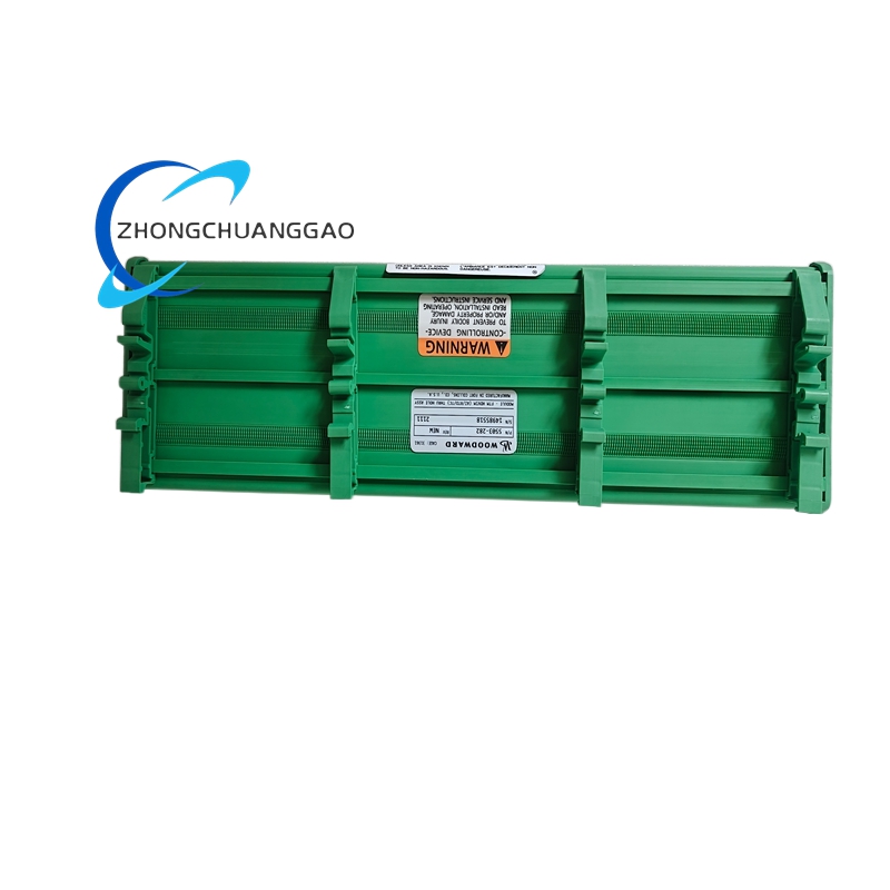
| Enclosure | Die-cast aluminum alloy (ADC12), powder-coated RAL 7032 (pebble gray) |
| Front Panel | Anodized aluminum with laser-etched labeling |
| PCB Board | FR-4 glass-epoxy laminate, conformal coated (UR5100), 4-layer design |
| Connectors | Mil-spec circular connectors (MIL-DTL-38999 Series III) for I/O |
| Terminal Blocks | Phoenix Contact or Wago spring-clamp terminals, UL listed, rated 300V/10A |
| Power Supply Module | Isolated DC-DC converter, encapsulated, UL recognized component |
| Trip Relay | Hermetically sealed reed relay, gold-plated contacts, 5A @ 250VAC rating |
| Auxiliary Relays | Solid-state relays (SSR) with zero-crossing detection, 3A @ 240VAC |
| Servo Output Transistors | IGBT (Insulated Gate Bipolar Transistor), rated 100V/5A per channel |
| Cable Glands | Nickel-plated brass, IP66/IP67 rated (PG11 or PG16) |
| Gaskets | Silicone rubber, operating range -40°C to +200°C |
| Mounting Hardware | Stainless steel 316L screws and washers |
| Heat Sink | Extruded aluminum fins, forced air or natural convection cooling |
| Shielding Gasket | Beryllium copper finger stock, EMI/RFI shielding |
| Internal Wiring | Teflon-insulated wire, rated 200°C, 22 AWG to 18 AWG |
| Fan (if equipped) | Brushless DC fan, 24 VDC, ball bearing, 40,000 hour MTBF |
Structural Features
- Compact DIN-rail mountable enclosure — fits standard 35mm top-hat rail or panel-mount with rear bracket
- Modular I/O architecture — removable terminal blocks for servo output, position feedback, power, and communication
- Front-accessible LED indicators — status LEDs for power, run, alarm, trip, servo channel 1, servo channel 2, and communication activity
- Sealed front panel — IP54 protection rating (dust and splash resistant)
- Rear cable entry — 6 cable glands (2× PG11 for position feedback, 2× PG16 for servo output, 2× PG11 for power/comm) with knockouts
- Vibration-damped mounting — internal rubber grommets isolate PCB from enclosure vibration
- EMC shielding — full metal enclosure with grounded shielding gasket between front and rear sections
- Service access — hinged front bezel allows terminal access without full panel removal
- Heat dissipation — internal heatsink fins on servo amplifier module, forced air cooling via brushless DC fan (24 VDC)
- Redundant configuration support — dual power input terminals for redundant 24 VDC supplies
- Test button — front-panel push button for trip relay verification test
- Position feedback terminals — dedicated LVDT/RVDT input terminals with automatic excitation selection
- Servo output terminals — heavy-gauge terminals rated for 10A continuous to actuator torque motor
- Fuse protection — internal 2A fast-blow fuse per servo channel for overcurrent protection
Working Principle
The Woodward 5503-282 operates as a digital closed-loop valve position controller with integrated servo amplifier. The microprocessor receives a valve position command signal (4-20 mA or ±50 mA) from the host governor (such as a Woodward 5437) via the command input. Simultaneously, the unit receives valve position feedback from an LVDT or RVDT sensor mounted on the actuator or valve stem. The LVDT signal is conditioned by the internal signal conditioning circuit, which provides automatic AC excitation at 2.5 kHz or 10 kHz and converts the AC position signal to a DC voltage proportional to valve stroke. The microprocessor compares the commanded position against the actual position feedback and calculates the position error. The onboard PID controller processes this error and generates a corrective current output sent to the IGBT servo amplifier stage. The servo amplifier delivers a ±250 mA current to the actuator torque motor, which generates a force proportional to the current. This force drives the hydraulic spool valve inside the servo actuator, which directs high-pressure hydraulic oil to one side of the actuator piston, moving the turbine valve to the commanded position. The LVDT continuously reports the new position back to the 5503-282, closing the loop. The unit also monitors servo current for overcurrent faults, position deviation for stuck valve detection, and communication status for governor signal loss. If any fault is detected, the trip relay de-energizes within 50 ms, sending a trip signal to the turbine trip solenoid. All events are time-stamped and stored in non-volatile flash memory and transmitted via Modbus RTU/TCP to the plant DCS or SCADA.
Advantages and Highlights
- Integrated servo amplifier — eliminates separate servo amplifier cabinet, reduces wiring by 60%, saves panel space
- Dual independent channels — supports main valve plus control valve from a single unit
- High output current ±250 mA — drives Woodward 9907/9903 actuators up to 10,000 lbf thrust without external amplification
- Built-in LVDT excitation — no external LVDT power supply required, auto-detects LVDT type
- Digital PID position control — eliminates mechanical positioner drift, provides tunable and repeatable valve control
- Drop-in replacement for Woodward 505F and 9907-010 — same footprint, same I/O wiring, same connector pinout
- SIL 2 certified (SIL 3 with redundancy) — meets functional safety requirements per IEC 61508
- Non-volatile event memory — retains 500 events through power loss, supports post-trip analysis
- Web-based configuration (GMT software) — full programming via standard Ethernet, no proprietary hardware tools
- Wide temperature range — operates from -20°C to +70°C, suitable for outdoor and harsh industrial environments
- Low power consumption — < 12 Watts, compatible with 24 VDC uninterruptible power supplies (UPS)
- Modbus RTU/TCP dual protocol — integrates with any DCS, PLC, or SCADA platform
- Front-panel relay test button — allows periodic trip relay verification without system shutdown
- Anti-windup PID — prevents integral windup during actuator saturation, ensures fast disturbance recovery
Applicable Industries
| Industry | Application |
|---|---|
| Power Generation | Steam turbine main steam valve control, reheat valve control, bypass valve control |
| Combined Cycle Plants | HRSG steam turbine valve positioning, backpressure turbine control |
| Nuclear Power | Steam turbine valve position control (non-safety-grade, per plant specifications) |
| Oil & Gas | Gas turbine fuel valve control, compressor driver turbine valve control |
| Chemical & Petrochemical | Turbo-compressor driver valve control, process steam turbine control |
| Pulp & Paper | Steam turbine-driven generators, black liquor recovery boiler turbines |
| District Heating | Steam turbine cogeneration plants, CHP valve control |
| Industrial Manufacturing | Turbine-driven blowers, fans, and process equipment valve control |
| Mining | Steam turbine-driven generators for mine power, compressor turbine control |
| Renewable Energy | Biomass steam turbine control, waste-to-energy steam turbines |
| Marine | Marine steam turbine valve control, propulsion turbine control |
| Desalination | Steam turbine-driven pumps, multi-effect distillation plant turbines |
Model Series Comparison (Woodward 5500 / 5503 Family)
| Model | Channels | Output Current | LVDT Input | Trip Relay | Communication | Drop-in For |
|---|---|---|---|---|---|---|
| 5503-272 | 1 (Single Channel) | ±150 mA | Yes (1 channel) | 1 | Modbus RTU | Woodward 505 |
| 5503-282 | 2 (Dual Channel) | ±250 mA | Yes (2 channels) | 1 | Modbus RTU/TCP | Woodward 505F |
| 5503-292 | 2 (Dual Channel) | ±250 mA | Yes (2 channels) | 1 | Modbus RTU/TCP + EtherNet/IP | Woodward 505F |
| 5503-302 | 2 (Dual Channel) | ±250 mA | Yes (2 channels) | 2 (redundant) | Modbus RTU/TCP + EtherNet/IP | Woodward 505F Redundant |
| 5503-312 | 2 (Dual Channel, ATEX) | ±250 mA | Yes (2 channels) | 1 | Modbus RTU/TCP | Woodward 505F (Hazardous Area) |
| 5503-322 | 2 (Dual Channel, SIL 3) | ±250 mA | Yes (2 channels) | 2 (redundant) | Modbus RTU/TCP + EtherNet/IP | Woodward 505F SIL 3 |
Installation Requirements
- Mounting Location: Install in a clean, dry, vibration-controlled environment within 0°C to +50°C ambient temperature
- Mounting Orientation: Vertical or horizontal DIN-rail mount; maintain minimum 2 inches (50 mm) clearance above and below unit for airflow
- Vibration Isolation: Use rubber vibration isolators if mounting surface vibration exceeds 2g RMS
- Power Wiring: Use shielded twisted-pair cable, 18 AWG minimum, for 24 VDC power input; connect positive and negative to designated terminals
- Command Input Wiring: Use shielded twisted-pair cable, 22 AWG minimum, from governor command output to 5503-282 input; maintain minimum 6 inches (150 mm) separation from power cables
- Position Feedback Wiring: Use shielded twisted-pair cable, 22 AWG minimum, from LVDT/RVDT to 5503-282 input; do not exceed 100 feet (30 m) without signal boosting
- Servo Output Wiring: Use shielded cable, 16 AWG minimum, from 5503-282 servo output to actuator torque motor; do not exceed 50 feet (15 m) without signal boosting
- Grounding: Connect chassis ground to plant equipment ground bus using green/yellow wire, minimum 14 AWG
- Cable Gland Torque: Tighten cable glands to 15 to 20 in-lbs (1.7 to 2.3 Nm) per manufacturer specification
- Communication Wiring: For Modbus RTU, use shielded twisted-pair, 22 AWG to 24 AWG, maximum 4,000 feet (1,200 m) at 9600 baud; for Modbus TCP, use Cat5e or Cat6 shielded Ethernet cable, maximum 100 meters (328 feet) per segment
- Redundant Power: For SIL 2/SIL 3 applications, connect dual 24 VDC power supplies to redundant power terminals
- Trip Relay Wiring: Use 14 AWG minimum wire for trip relay contacts; wire to turbine trip solenoid per OEM specifications
- LVDT Wiring: Use shielded twisted-pair cable, 22 AWG minimum; do not mix LVDT wires with power cables in the same conduit
- Environmental Sealing: Install IP66-rated cable glands if unit is exposed to moisture or dust
- Clearance: Maintain minimum 6 inches (150 mm) clearance from high-voltage cables (> 600 VAC)
- Actuator Compatibility: Verify actuator model is Woodward 9907, 9903, 9907A, or 9903A before connecting servo output
- LVDT Compatibility: Verify LVDT type is ±10 VAC or 4-20 mA; do not connect 0-10 VDC LVDTs without signal converter
Usage Precautions and Notes
- Never apply power to the 5503-282 without all I/O connections properly terminated — open position feedback loops cause false position readings and unstable valve control
- Verify LVDT polarity before energizing — incorrect polarity causes erratic position display and unstable control
- Do not exceed ±250 mA on servo output channels — overcurrent damages the IGBT output stage and actuator torque motor
- Do not exceed 15 VAC on LVDT input channels — overvoltage damages the LVDT signal conditioning circuit
- Replace the 24 VDC power supply filter capacitor every 5 years — electrolytic capacitors degrade over time and cause power supply ripple
- Perform a full functional test including position deviation alarm every 12 months per API 670 and NFPA 85 requirements
- Do not modify firmware without Woodward-authorized service personnel — unauthorized firmware changes void SIL certification
- Lock the front panel after configuration using the provided security screws to prevent unauthorized parameter changes
- Record all configuration changes in the plant maintenance log — include date, technician name, and parameter values changed
- Do not operate the 5503-282 with the front bezel removed — exposure to live terminals creates electrical hazard
- Verify communication settings (baud rate, node address, protocol) match the governor configuration before connecting to the network
- In the event of a position feedback signal loss, the 5503-282 will trip on position deviation — this is a failsafe design, not a fault condition
- Do not use the 5503-282 for safety-instrumented functions without SIL certification verification — confirm SIL rating matches the application safety integrity level
- Battery backup for 24 VDC power is mandatory for SIL 2/SIL 3 installations — power loss must not cause uncontrolled turbine shutdown
- Store spare units in a climate-controlled environment, 10°C to 35°C, with desiccant packs — moisture ingress damages PCB conformal coating
- Calibrate LVDT sensors annually — LVDT drift causes position control inaccuracy over time
- All installation and commissioning must be performed by a certified Woodward service technician or authorized third-party integrator per Woodward installation manual WM-0025
- When using the 5503-282 with a Woodward 5437 governor, verify the governor command output is configured for 4-20 mA or ±50 mA — mismatch causes governor fault
- Do not connect the 5503-282 analog output to a DCS input with a different signal range — 4-20 mA to 4-20 mA only; do not connect to 0-10 VDC inputs without a signal converter
- The 5503-282 provides LVDT excitation; do not apply external LVDT power to the same sensor — dual power sources damage the LVDT
- Servo output cables must be routed separately from control signal cables — electromagnetic interference from servo cables corrupts position feedback signals
- Verify actuator torque motor resistance matches the 5503-282 output rating — connecting an actuator with resistance outside the specified range causes overheating or insufficient drive current
- Do not bypass the internal fuse on any servo channel — the fuse protects the IGBT output stage from catastrophic failure

Reviews
There are no reviews yet.