Product Short Description
The Woodward 5448-890 SPM-D10 is a digital steam pressure monitor designed for steam turbine control applications where direct speed feedback is unavailable or unreliable. It replaces legacy pneumatic pressure monitors and provides dual-channel pressure-based speed derivation for turbine speed regulation. The unit accepts two independent 4-20 mA pressure transmitter inputs from steam chest or reheat steam pressure sensors and calculates turbine speed using a programmable pressure-to-speed correlation curve.
Description
Technical Specifications
| Parameter | Specification |
|---|---|
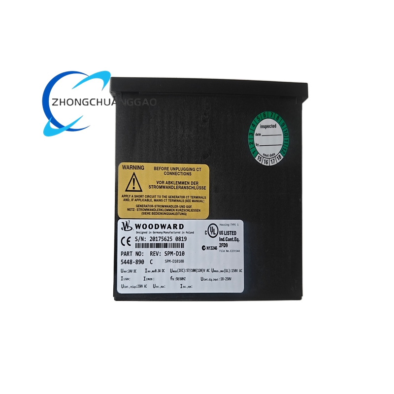
| Model Number | 5448-890 |
| Module Designation | SPM-D10 |
| Series | 5448 Series |
| Monitor Type | Digital Steam Pressure Monitor, Dual-Channel |
| Pressure Input Channels | 2 independent channels (CH1, CH2) |
| Pressure Input Signal | 4-20 mA, 2-wire loop powered |
| Pressure Input Impedance | 250 Ohms nominal per channel |
| Pressure Range (Configurable) | 0 to 500 psig (0 to 34.5 bar) full scale, programmable |
| Pressure Accuracy | ±0.25% of full scale (typical) |
| Pressure Resolution | 16-bit ADC, 0.004% of full scale |
| Speed Derivation Method | Programmable pressure-to-speed curve (polynomial or table lookup) |
| Derived Speed Range | 0 to 6,000 RPM (configurable) |
| Derived Speed Accuracy | ±0.5% of rated speed (steady state) |
| Trip Outputs | 2 independent Form C trip relays (overpressure, underpressure) |
| Trip Relay Rating | 5A @ 250VAC, 5A @ 30VDC |
| Trip Logic | De-energize-to-trip (fail-safe) or energize-to-trip (configurable) |
| Alarm Relay Outputs | 4 programmable Form C alarm relays |
| Alarm Relay Rating | 3A @ 250VAC, 3A @ 30VDC |
| Analog Output | 1 configurable 4-20 mA output (pressure or derived speed) |
| Communication Protocols | Modbus RTU (RS-485), Modbus TCP (Ethernet), EtherNet/IP |
| Power Supply | 24 VDC nominal, 18 VDC to 30 VDC operating range |
| Power Consumption | < 6 Watts (typical) |
| Operating Temperature | -20°C to +70°C (-4°F to +158°F) |
| Storage Temperature | -40°C to +85°C (-40°F to +185°F) |
| Humidity Range | 5% to 95% non-condensing |
| Vibration Tolerance | 5g peak, 10 Hz to 200 Hz (per IEC 60068-2-6) |
| Shock Tolerance | 15g, 11 ms half-sine (per IEC 60068-2-27) |
| EMC Compliance | IEC 61000-6-2 (industrial), IEC 61000-6-4 (emission) |
| Dimensions (H × W × D) | Approximately 9.5 in × 7.0 in × 5.5 in (241 mm × 178 mm × 140 mm) |
| Weight | Approximately 3.0 lbs (1.4 kg) |
| Mounting | Panel-mount, DIN rail, or direct wall-mount with brackets |
| Certifications | CE Marked, ATEX Zone 2 (optional), UL/CSA listed (variant dependent) |
| SIL Rating | SIL 2 (per IEC 61508, SIL 3 achievable with redundant configuration) |
| Drop-in Replacement For | Woodward 1701, 1701A, 1701B pneumatic pressure monitors |
Functional Features
- Dual independent pressure input channels (CH1 and CH2) — supports primary/backup pressure sensing or dual-point steam chest monitoring
- Digital pressure-to-speed derivation — calculates turbine speed from steam pressure using programmable correlation curve without requiring a speed probe
- Dual overpressure trip — independent hardware trip for each channel, de-energizes turbine trip solenoid if pressure exceeds preset limit
- Dual underpressure trip — independent hardware trip for each channel, de-energizes turbine trip solenoid if pressure falls below preset limit
- Programmable pressure alarm relays — 4 relays configurable for high-high, high, low-low, low pressure alarms with independent setpoints
- Built-in pressure transmitter excitation — provides 24 VDC loop power to 4-20 mA pressure transmitters, eliminates external power supply
- Analog output channel — configurable 4-20 mA output for real-time pressure or derived speed transmission to DCS/SCADA
- Modbus RTU/TCP and EtherNet/IP communication — seamless integration with plant DCS, PLC, or SCADA systems
- Event logging — onboard non-volatile memory stores up to 500 time-stamped events including trip history and alarm sequences
- Self-diagnostics — continuous monitoring of pressure input signal quality, loop integrity, internal CPU health, and relay status
- Speed signal backup — when used with Woodward 5437 governor, the SPM-D10 provides a derived speed backup signal if primary speed probe fails
- Pressure sensor fault detection — detects open circuit, short circuit, and out-of-range conditions on both input channels
- Trip relay test function — built-in relay test button for periodic verification without taking the unit offline
- Web-based configuration — full parameter programming via Woodward GMT (Governor Management Tool) software over Ethernet
- Redundant configuration support — dual power input terminals for redundant 24 VDC supplies in SIL 3 applications
Performance Parameters
| Parameter | Value |
|---|---|
| Pressure Measurement Accuracy | ±0.25% of full scale (typical), ±0.5% maximum |
| Pressure Response Time | < 100 ms (10% to 90% of step change) |
| Derived Speed Accuracy | ±0.5% of rated speed (steady state) |
| Derived Speed Response Time | < 500 ms (from pressure step to speed output update) |
| Overpressure Trip Accuracy | ±0.5% of trip setpoint |
| Underpressure Trip Accuracy | ±0.5% of trip setpoint |
| Trip Response Time | < 50 ms from trip condition detection to relay activation |
| Pressure Input Noise Rejection | > 60 dB common-mode rejection |
| Analog Output Resolution | 16-bit DAC, 0.0015% full scale |
| Communication Update Rate | 10 ms to 100 ms (configurable per protocol) |
| Warm-up Time to Operational | < 30 seconds from power-on |
| Maximum Pressure Input Frequency | 10 Hz (supports fast transient pressure monitoring) |
| Minimum Pressure Input Signal | 3.5 mA (detects open circuit below 3.5 mA) |
| Maximum Pressure Input Signal | 22 mA (detects overrange above 22 mA) |
| Loop Power Supply Voltage | 24 VDC ± 10% |
| Loop Power Supply Current Capacity | Up to 100 mA per channel (sufficient for most 4-20 mA transmitters) |
Material Composition
| Component | Material |
|---|---|
| Enclosure | Die-cast aluminum alloy (ADC12), powder-coated RAL 7032 (pebble gray) |
| Front Panel | Anodized aluminum with laser-etched labeling |
| PCB Board | FR-4 glass-epoxy laminate, conformal coated (UR5100), 4-layer design |
| Connectors | Mil-spec circular connectors (MIL-DTL-38999 Series III) for I/O |
| Terminal Blocks | Phoenix Contact or Wago spring-clamp terminals, UL listed, rated 300V/10A |
| Power Supply Module | Isolated DC-DC converter, encapsulated, UL recognized component |
| Trip Relays | Hermetically sealed reed relays, gold-plated contacts, 5A @ 250VAC rating |
| Alarm Relays | Solid-state relays (SSR) with zero-crossing detection, 3A @ 240VAC |
| Cable Glands | Nickel-plated brass, IP66/IP67 rated (PG11 or PG16) |
| Gaskets | Silicone rubber, operating range -40°C to +200°C |
| Mounting Hardware | Stainless steel 316L screws and washers |
| Heat Sink | Extruded aluminum fins, natural convection cooling |
| Shielding Gasket | Beryllium copper finger stock, EMI/RFI shielding |
Structural Features
- Compact DIN-rail mountable enclosure — fits standard 35mm top-hat rail or panel-mount with rear bracket
- Modular I/O architecture — removable terminal blocks for pressure input, trip output, alarm output, power, and communication
- Front-accessible LED indicators — status LEDs for power, run, alarm, trip, pressure channel 1, pressure channel 2, and communication activity
- Sealed front panel — IP54 protection rating (dust and splash resistant)
- Rear cable entry — 4 cable glands (2× PG11 for pressure input/output, 2× PG16 for power/comm) with knockouts
- Vibration-damped mounting — internal rubber grommets isolate PCB from enclosure vibration
- EMC shielding — full metal enclosure with grounded shielding gasket between front and rear sections
- Service access — hinged front bezel allows terminal access without full panel removal
- Heat dissipation — internal heatsink fins on power module, natural convection cooling (no fan required)
- Redundant configuration support — dual power input terminals for redundant 24 VDC supplies
- Test button — front-panel push button for trip relay verification test
- Loop power terminals — dedicated 24 VDC output terminals for pressure transmitter excitation
Working Principle
The Woodward 5448-890 SPM-D10 operates as a digital dual-channel steam pressure monitor with pressure-derived speed calculation. The microprocessor continuously samples two independent 4-20 mA pressure signals from steam chest or reheat steam pressure transmitters via the internal 16-bit analog-to-digital converters (ADCs). Each channel is independently scaled from raw current to engineering units (psig or bar) using programmable calibration constants. The unit applies a programmable pressure-to-speed correlation curve (stored in non-volatile memory as a polynomial equation or lookup table) to convert the measured steam pressure into a derived turbine speed value. This derived speed is compared against programmable overspeed and underspeed trip setpoints. If the derived speed exceeds the overspeed trip limit or falls below the underspeed trip limit, the corresponding hardware trip relay de-energizes within 50 ms, sending a trip signal to the turbine trip solenoid. Simultaneously, the unit monitors each pressure input for open circuit, short circuit, and out-of-range faults. If a pressure sensor fault is detected, the unit activates the appropriate alarm relay and logs the event. The 4-20 mA analog output transmits the real-time pressure or derived speed to the plant DCS or SCADA. All events, alarms, and trip conditions are time-stamped and stored in non-volatile flash memory and transmitted via Modbus RTU/TCP or EtherNet/IP to the plant control system. When integrated with a Woodward 5437 governor, the SPM-D10 provides a derived speed backup signal that the governor uses for speed control if the primary magnetic pickup speed signal is lost.
Advantages and Highlights
- Dual-channel pressure monitoring — provides redundancy and cross-checking for critical steam turbine protection
- Pressure-derived speed control — enables turbine speed regulation without a speed probe, ideal for retrofit applications
- Drop-in replacement for Woodward 1701/1701A/1701B — same footprint, same I/O wiring, same connector pinout, zero redesign required
- Built-in loop power for pressure transmitters — eliminates external 24 VDC power supply for 4-20 mA transmitters
- SIL 2 certified (SIL 3 with redundancy) — meets functional safety requirements for steam turbine overspeed protection per IEC 61508
- Independent hardware trip outputs — overpressure and underpressure trips operate independently of software, providing failsafe operation
- Non-volatile event memory — retains 500 events through power loss, supports post-trip analysis
- Web-based configuration (GMT software) — full programming via standard Ethernet, no proprietary hardware tools required
- Wide temperature range — operates from -20°C to +70°C, suitable for outdoor and harsh industrial environments
- Low power consumption — < 6 Watts, compatible with 24 VDC uninterruptible power supplies (UPS)
- Modbus and EtherNet/IP dual protocol — integrates with any DCS, PLC, or SCADA platform
- No moving parts in control loop — zero mechanical wear, maintenance-free pressure sensing
- Front-panel relay test button — allows periodic trip relay verification without system shutdown
Applicable Industries
| Industry | Application |
|---|---|
| Power Generation | Steam turbine overspeed protection, pressure-derived speed control in fossil fuel plants |
| Combined Cycle Plants | HRSG steam turbine pressure monitoring, backpressure turbine control |
| Nuclear Power | Steam turbine pressure backup protection (non-safety-grade, per plant specifications) |
| Oil & Gas | Steam-driven compressor turbine monitoring, cogeneration plant steam turbines |
| Chemical & Petrochemical | Process steam turbine pressure control,背压 turbine monitoring |
| Pulp & Paper | Steam turbine-driven generators, black liquor recovery boiler turbines |
| District Heating | Steam turbine cogeneration plants, CHP systems |
| Industrial Manufacturing | Steam-driven process turbines, paper machine drives |
| Mining | Steam turbine-driven generators for mine power |
| Renewable Energy | Biomass steam turbine control, waste-to-energy steam turbines |
Model Series Comparison (Woodward 5448 Family)
| Model | Channels | Pressure Input | Derived Speed | Trip Outputs | Communication | Drop-in For |
|---|---|---|---|---|---|---|
| 5448-870 | 1 (Single Channel) | 4-20 mA | Yes | 1 trip + 2 alarm | Modbus RTU | Woodward 1701 |
| 5448-880 | 1 (Single Channel) | 4-20 mA | Yes | 1 trip + 4 alarm | Modbus RTU/TCP | Woodward 1701A |
| 5448-890 SPM-D10 | 2 (Dual Channel) | 4-20 mA × 2 | Yes | 2 trip + 4 alarm | Modbus RTU/TCP + EtherNet/IP | Woodward 1701B |
| 5448-900 | 2 (Dual Channel) | 4-20 mA × 2 | Yes | 2 trip + 4 alarm | Modbus RTU/TCP + EtherNet/IP | Woodward 1701B |
| 5448-910 | 2 (Dual Channel, Redundant) | 4-20 mA × 2 | Yes | 2 trip (redundant) + 4 alarm | Modbus RTU/TCP + EtherNet/IP | Woodward 1701B Redundant |
| 5448-920 | 2 (Dual Channel, ATEX) | 4-20 mA × 2 | Yes | 2 trip + 4 alarm | Modbus RTU/TCP + EtherNet/IP | Woodward 1701B (Hazardous Area) |
Installation Requirements
- Mounting Location: Install in a clean, dry, vibration-controlled environment within 0°C to +50°C ambient temperature
- Mounting Orientation: Vertical or horizontal DIN-rail mount; maintain minimum 2 inches (50 mm) clearance above and below unit for airflow
- Vibration Isolation: Use rubber vibration isolators if mounting surface vibration exceeds 2g RMS
- Power Wiring: Use shielded twisted-pair cable, 18 AWG minimum, for 24 VDC power input; connect positive and negative to designated terminals
- Pressure Input Wiring: Use shielded twisted-pair cable, 22 AWG minimum, from 4-20 mA pressure transmitter to SPM-D10 input; maintain minimum 6 inches (150 mm) separation from power cables
- Trip Relay Wiring: Use 14 AWG minimum wire for trip relay contacts; wire to turbine trip solenoid per OEM specifications
- Alarm Relay Wiring: Use 18 AWG minimum wire for alarm relay contacts; wire to annunciator panel or DCS digital input
- Analog Output Wiring: Use shielded twisted-pair cable, 22 AWG minimum, from 4-20 mA output to DCS/SCADA analog input; maximum 1,000 feet (300 m) without signal booster
- Grounding: Connect chassis ground to plant equipment ground bus using green/yellow wire, minimum 14 AWG
- Cable Gland Torque: Tighten cable glands to 15 to 20 in-lbs (1.7 to 2.3 Nm) per manufacturer specification
- Communication Wiring: For Modbus RTU, use shielded twisted-pair, 22 AWG to 24 AWG, maximum 4,000 feet (1,200 m) at 9600 baud; for EtherNet/IP, use Cat5e or Cat6 shielded Ethernet cable, maximum 100 meters (328 feet) per segment
- Redundant Power: For SIL 2/SIL 3 applications, connect dual 24 VDC power supplies to redundant power terminals
- Loop Power Wiring: The SPM-D10 provides 24 VDC loop power to pressure transmitters; verify transmitter loop resistance does not exceed 600 Ohms per channel
- Environmental Sealing: Install IP66-rated cable glands if unit is exposed to moisture or dust
- Clearance: Maintain minimum 6 inches (150 mm) clearance from high-voltage cables (> 600 VAC)
- Pressure Transmitter Selection: Use 4-20 mA, 2-wire transmitters with HART protocol optional; verify transmitter range matches SPM-D10 configured range
Usage Precautions and Notes
- Never apply power to the SPM-D10 without all pressure input loops properly terminated — open 4-20 mA loops cause false overpressure readings and unintended trips
- Verify pressure transmitter polarity before energizing — incorrect polarity causes erratic pressure display and unstable derived speed
- Do not exceed 24 mA on pressure input channels — overcurrent damages the input protection circuit
- Do not exceed 600 Ohms total loop resistance per channel — excessive resistance causes inaccurate pressure measurement
- Replace the 24 VDC power supply filter capacitor every 5 years — electrolytic capacitors degrade over time and cause power supply ripple
- Perform a full functional test including overpressure trip every 12 months per API 670 and NFPA 85 requirements
- Do not modify firmware without Woodward-authorized service personnel — unauthorized firmware changes void SIL certification
- Lock the front panel after configuration using the provided security screws to prevent unauthorized parameter changes
- Record all configuration changes in the plant maintenance log — include date, technician name, and parameter values changed
- Do not operate the SPM-D10 with the front bezel removed — exposure to live terminals creates electrical hazard
- Verify communication settings (baud rate, node address, protocol) match the DCS/SCADA configuration before connecting to the network
- In the event of a pressure input signal loss, the SPM-D10 will trip on underpressure — this is a failsafe design, not a fault condition
- Do not use the SPM-D10 for safety-instrumented functions without SIL certification verification — confirm SIL rating matches the application safety integrity level
- Battery backup for 24 VDC power is mandatory for SIL 2/SIL 3 installations — power loss must not cause uncontrolled turbine shutdown
- Store spare units in a climate-controlled environment, 10°C to 35°C, with desiccant packs — moisture ingress damages PCB conformal coating
- Calibrate pressure transmitters annually — transmitter drift causes derived speed inaccuracy over time
- All installation and commissioning must be performed by a certified Woodward service technician or authorized third-party integrator per Woodward installation manual WM-0020
- When using derived speed as a backup to a Woodward 5437 governor, verify the governor is configured to accept the SPM-D10 speed input — mismatch causes governor fault
- Do not connect the SPM-D10 analog output to a DCS input with a different signal range — 4-20 mA to 4-20 mA only; do not connect to 0-10 VDC inputs without a signal converter
- Pressure transmitter loop power is provided by the SPM-D10; do not apply external loop power to the same transmitter — dual power sources damage the transmitter

Reviews
There are no reviews yet.