Product Short Description
Product Overview
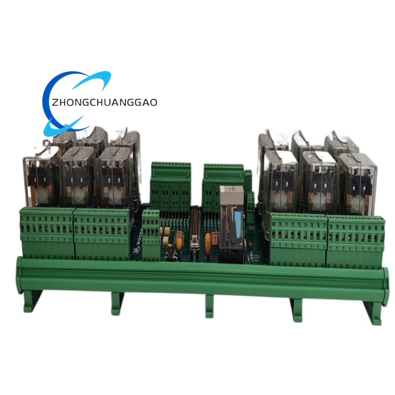
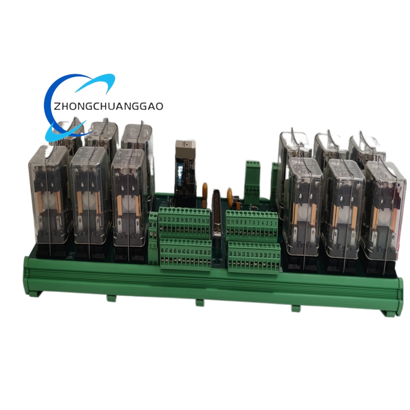
The Woodward 5441-693 is a solid-state electronic speed and load governor designed for diesel and gas engine applications. It replaces legacy mechanical and electro-hydraulic governors with a fully digital control platform. The unit provides precise engine speed regulation, load sharing, and engine protection functions in a single compact package.
Description
Key Functions
- Engine Speed Control — Maintains setpoint speed under varying load conditions
- Load Sharing / Droop Control — Enables parallel operation of multiple generators with accurate load distribution
- Overspeed Protection — Automatically shuts down the engine if speed exceeds a preset safety limit
- Under-Speed Protection — Trips the engine if speed drops below a minimum threshold
- Fuel Limiting — Restricts maximum fuel delivery to prevent engine damage
- Starting Control — Manages crank and run fuel quantities during engine start sequences
- Governor Alarm Outputs — Provides relay contacts for alarm and shutdown signaling
Technical Specifications
| Parameter | Value |
|---|---|
| Input Voltage Range | 18 VDC to 32 VDC (nominal 24 VDC) |
| Frequency Input Range | 0 Hz to 2000 Hz (from magnetic pickup or MPU) |
| Speed Setpoint Input | 0.5 VDC to 4.5 VDC (analog) or digital setpoint via communications |
| Load Reference Input | 0 VDC to 5 VDC or 4 mA to 20 mA |
| Output Type | PWM (Pulse Width Modulation) for actuator drive |
| PWM Frequency | 125 Hz (fixed) |
| PWM Duty Cycle Range | 0% to 100% |
| Operating Temperature | -40°C to +85°C (-40°F to +185°F) |
| Storage Temperature | -55°C to +125°C (-67°F to +257°F) |
| Humidity Rating | 5% to 95% non-condensing |
| Vibration Rating | Conforms to IEC 60068-2-6 |
| Altitude Rating | Up to 10,000 ft (3,048 m) without derating |
| EMC Compliance | IEC 61000-6-2 (Industrial Environment) |
| Enclosure Protection | IP54 (front panel), conformally coated PCB |
| Weight | Approximately 0.7 kg (1.5 lbs) |
| Dimensions (L x W x H) | Approximately 180 mm x 120 mm x 60 mm |
Actuator Output Specifications
| Parameter | Value |
|---|---|
| Maximum Drive Current | 8 A continuous |
| Peak Drive Current | 12 A (5 seconds max) |
| PWM Output Polarity | Sourcing or sinking (configurable) |
| Actuator Type Compatibility | Magnetic actuators, coil-type solenoids |
| Response Time (Speed to 90%) | Less than 100 ms |
Communication Interfaces
| Interface | Protocol |
|---|---|
| RS-485 Serial | Modbus RTU (default), Woodward CAN |
| Discrete Inputs | 8 dry contact inputs (configurable for alarms, enable, mode select) |
| Discrete Outputs | 4 relay outputs (configurable for alarm, shutdown, status) |
| Analog Inputs | 4 configurable (speed, load reference, auxiliary) |
| Analog Outputs | 2 configurable (speed indication, load indication) |
Drop / Isochronous Modes
| Mode | Droop Setting | Application |
|---|---|---|
| Isochronous | 0% droop | Single generator, grid-connected or isolated bus |
| Droop | 3% to 10% selectable | Parallel generator load sharing |
| Programmable Droop | 0% to 10% via digital interface | Custom load sharing requirements |
Protection Features
- Overspeed Shutdown — Configurable trip point, adjustable delay (0 to 30 seconds)
- Underspeed Shutdown — Configurable trip point, adjustable delay
- Overspeed Alarm — Relay output activates before trip point
- Fail-Safe Operation — On loss of speed signal, output drives to safe position (fuel cut or full fuel depending on configuration)
- Loss of Actuator Feedback Alarm — Detects open/short circuit in actuator coil
- Supply Voltage Monitoring — Low voltage and high voltage alarm thresholds configurable
Material Composition
| Component | Material |
|---|---|
| Housing | Die-cast aluminum alloy with powder-coat finish |
| Front Panel | Polycarbonate with membrane keypad overlay |
| PCB | FR-4 fiberglass epoxy, conformally coated |
| Connectors | Industrial-grade screw terminal blocks, tin-plated copper |
| Mounting Brackets | Stainless steel 304 |
Structural Features
- DIN rail mountable (35 mm top-hat rail)
- Front-accessible terminal blocks for wiring
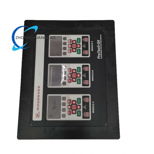
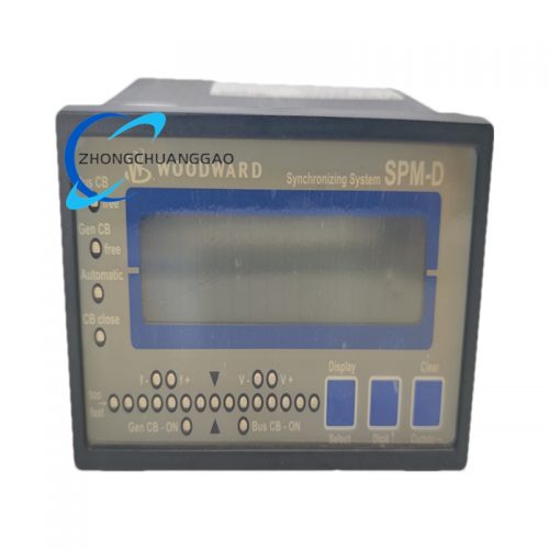
- Membrane keypad with LCD display for local configuration
- LED status indicators (Power, Run, Alarm, Fault)
- Configurable via front panel or remote via Modbus/CAN
Working Principle
The 5441-693 receives a frequency signal from a magnetic pickup sensor mounted on the engine flywheel or gear. The internal microcontroller converts the frequency to engine RPM and compares it to the setpoint speed. The error signal is processed through a PID (Proportional-Integral-Derivative) control algorithm. The controller outputs a PWM signal to the fuel actuator, adjusting fuel rack position to minimize the speed error. For load sharing, the controller adjusts the speed setpoint based on the load reference input, creating a controlled droop characteristic.
Advantages and Highlights
- Fully Digital Architecture — No mechanical linkages, no wear parts in the controller
- High Precision — Speed regulation within ±0.1% of setpoint
- Fast Response — Sub-100 ms transient response
- Remote Configuration — Full parameter set via Modbus RTU or Woodward CAN
- Wide Input Compatibility — Supports MPU, variable reluctance, and Hall-effect speed sensors
- Redundant Protection — Multiple independent overspeed and underspeed protection channels
- Compact Footprint — Fits in standard DIN rail enclosures
- Long Service Life — No mechanical fatigue, MTBF exceeds 50,000 hours
Applicable Industries
- Power Generation — Diesel and gas generator sets (standby, prime, continuous)
- Marine Propulsion — Auxiliary and main engine governors
- Oil and Gas — Compressor drivers, pump drivers, wellhead power units
- Mining — Diesel generator sets for underground and surface operations
- Rail — Auxiliary power units (APUs)
- Industrial — Any diesel/gas engine requiring electronic speed control
Compatible Actuator Models (Woodward)
| Actuator | Type |
|---|---|
| 9907-167 | Magnetic, 24 VDC |
| 9907-168 | Magnetic, 12/24 VDC |
| 9930-823 | High-force magnetic |
| 9907-046 | Low-force magnetic |
Installation Requirements
- Mount on 35 mm DIN rail in a location free from excessive vibration and direct heat sources
- Maintain minimum 50 mm clearance on all sides for ventilation
- Route speed sensor cable away from high-current power cables (minimum 150 mm separation)
- Use shielded twisted-pair cable for speed signal (minimum 0.5 mm² cross-section)
- Ground the controller chassis to the engine block ground point
- Supply voltage must be filtered; use a 24 VDC regulated supply with less than 5% ripple
- Torque all terminal connections to 1.2 Nm (10.6 in-lbs)
Usage Precautions
- Do not exceed the maximum supply voltage of 32 VDC — permanent damage will occur
- Do not reverse the polarity of the power supply — internal fuse will blow
- Verify speed sensor air gap is within 0.3 mm to 1.5 mm (0.012″ to 0.060″) before startup
- Perform a no-load speed calibration after initial installation
- Do not operate the unit in environments exceeding +85°C ambient temperature
- Replace the conformal coating if the PCB is exposed to chemical solvents
- Perform a functional test of all protection relays every 6 months
- Do not modify the firmware using unauthorized tools — this voids the warranty
- The unit contains no user-serviceable components — contact Woodward for repairs
Model Series Cross-Reference
| Model | Key Difference from 5441-693 |
|---|---|
| 5441-611 | Basic speed control, no load sharing |
| 5441-691 | Isochronous only, no droop capability |
| 5441-693 | Full-featured: speed control, droop, load sharing, dual protection |
| 5441-793 | Extended communication (Ethernet/CAN) |
Certifications and Compliance
- CE Marking — Conforms to EU Machinery Directive 2006/42/EC
- UL Listed — File E147353 (for North American installations)
- CSA Certified — File LR78161
- DNV GL Type Approval — For marine applications
- Lloyd’s Register — Approved for marine generator sets
- ATEX — Not rated for hazardous area use (use 5441-Ex variants for ATEX zones)
Part Number Breakdown
| Segment | Meaning |
|---|---|
| 5441 | Product family — Electronic Governor |
| 6 | Feature set — Full function with droop and load share |
| 93 | Region/Configuration code — Global standard configuration, 24 VDC, Modbus RTU |
Warranty
- Standard Warranty: 24 months from date of shipment
- Extended Warranty: Available up to 60 months (Woodward Protect program)
Document Reference Numbers
| Document | Number |
|---|---|
| Installation Manual | 5441-IM-001 |
| Operator’s Manual | 5441-OM-001 |
| Configuration Guide | 5441-CG-001 |
| Wiring Diagram | 5441-WD-001 |
Reviews
There are no reviews yet.