Product Short Description
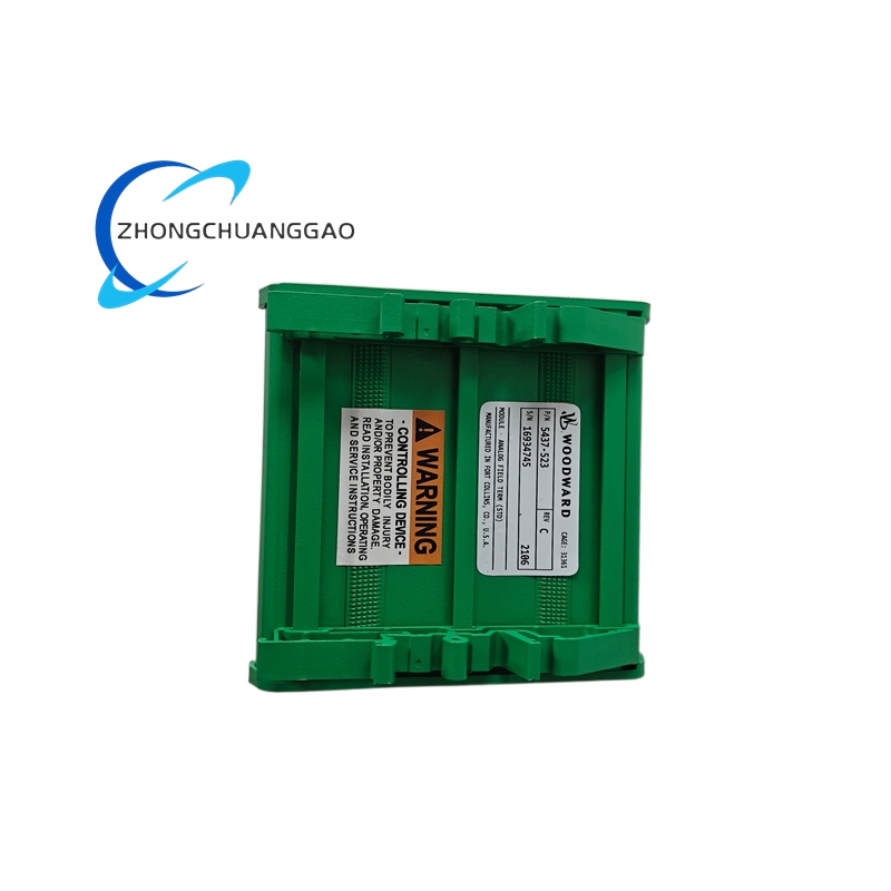
The Woodward 5437-523 is a solid-state digital automatic voltage regulator (AVR) designed to control the output voltage of brushless AC generators (alternators). It is a microprocessor-based excitation control module that replaces older analog-type regulators. The unit senses generator terminal voltage, compares it to a reference, and adjusts the exciter field current to maintain constant output voltage under varying load conditions. It is engineered for reliability, accuracy, and adaptability across industrial power generation applications. The 5437-523 is part of the Woodward 5437 Series digital regulators, widely deployed in standby, prime, and continuous power systems.
Description
Model Series
| Model | Series | Key Variant |
|---|---|---|
| 5437-523 | 5437 Series | Standard digital AVR, 3-phase sensing |
| 5437-513 | 5437 Series | Single-phase sensing variant |
| 5437-533 | 5437 Series | High-current exciter output variant |
| 5437-543 | 5437 Series | Dual-setpoint variant |
| 5437-501 | 5437 Series | Legacy analog-hybrid predecessor |
| 5401 | EasyGen Series | Lower-cost AVR for smaller gensets |
| 5466 | EasyGen Series | Multi-function controller (AVR + governor) |
| 5500 | Proseries | High-performance digital controller |
Technical Specifications
| Parameter | Value |
|---|---|
| Regulator Type | Digital Automatic Voltage Regulator (AVR) |
| Input Voltage Sensing | 3-phase, 120 VAC to 600 VAC (line-to-line) |
| Frequency Range | 45 Hz to 65 Hz |
| Output Excitation Current | Up to 10 A continuous (DC) |
| Output Excitation Voltage | Up to 300 VDC maximum |
| Voltage Regulation Accuracy | ±1% of setpoint (typical), ±0.5% (optimal conditions) |
| Voltage Setpoint Range | 90 VAC to 130 VAC (adjustable via potentiometer or software) |
| Response Time (transient) | <50 ms for 100% load step |
| Stability | Stable with capacitive loads up to 10 μF |
| Operating Temperature | -20°C to +70°C (-4°F to +158°F) |
| Storage Temperature | -40°C to +85°C (-40°F to +185°F) |
| Power Supply | Self-powered from generator terminals (no external supply required) |
| Mounting | DIN rail or panel mount (standard 35 mm DIN rail) |
| Dimensions (Approx.) | 120 mm × 90 mm × 110 mm (H × W × D) |
| Weight (Approx.) | 0.8 kg (1.76 lbs) |
| Communication Interface | RS-485 (Modbus RTU), optional USB, analog output |
| Certifications | UL 508, CE, CSA, IEC 61000-6-2, IEC 61000-6-4 |
Functional Features
- Digital microprocessor control replaces analog circuitry for superior accuracy and drift-free operation
- 3-phase voltage sensing with phase-loss detection and phase-rotation indication
- Adjustable voltage setpoint via front-panel potentiometer or remote digital command
- Under-voltage and over-voltage protection with configurable trip thresholds
- Over-excitation and under-excitation limiting to protect generator and exciter windings
- Soft-start function for controlled voltage buildup on generator startup
- Stability compensation for capacitive and inductive loads (adjustable gain)
- Droop compensation for parallel generator operation (load sharing)
- Remote sensing capability for compensating voltage drop across long cable runs
- LED status indicators for power, fault, voltage regulation, and alarm states
- RS-485 Modbus RTU communication for integration with SCADA, BMS, or remote monitoring
- Analog output (4–20 mA or 0–10 VDC) proportional to terminal voltage for external monitoring
- Fault memory stores last 10 alarm events with timestamps
- Adjustable voltage regulation bandwidth to match generator and load dynamics
- Phase loss detection — automatically reduces excitation if one phase is lost to prevent damage
- Built-in surge protection on all input and output terminals
Performance Parameters
| Parameter | Specification |
|---|---|
| Voltage Regulation (steady-state) | ±1% of nominal (95 VAC to 105 VAC at 100 VAC setpoint) |
| Transient Response (100% load step) | <50 ms recovery to ±2% |
| Frequency Response | 45 Hz to 65 Hz (maintains regulation across full range) |
| Temperature Drift | <0.01% per °C (after warm-up) |
| Line Voltage Effect | <0.1% output change per 10% input voltage variation |
| Load Effect (reactive) | <0.5% voltage change from no-load to full-load at 0.8 PF lagging |
| Harmonic Distortion (output) | <2% THD at full load |
| Insulation Resistance | >100 MΩ at 500 VDC (between terminals and chassis) |
| Dielectric Strength | 2000 VAC RMS for 1 minute (input to chassis) |
| MTBF (Mean Time Between Failures) | >100,000 hours (at 25°C ambient) |
| Exciter Field Current Output | 0 to 10 A DC continuous (rated) |
| Exciter Field Voltage Output | 0 to 300 VDC maximum |
| Control Loop Bandwidth | Adjustable: 1 Hz to 50 Hz (typical setting: 5–10 Hz) |
Material Composition
| Component | Material |
|---|---|
| Enclosure / Housing | Flame-retardant polycarbonate (UL 94 V-0 rated) |
| PCB (Printed Circuit Board) | FR-4 glass epoxy, conformal coated |
| Terminal Blocks | Phosphor bronze, tin-plated, screw-clamp type |
| Connector Pins | Gold-plated brass |
| Mounting Bracket | Galvanized steel, powder-coated |
| Potentiometer (setpoint) | Cermet, sealed, multi-turn |
| LED Indicators | High-brightness epoxy-encapsulated LEDs (red, green, yellow) |
| Internal Wiring | Tinned copper, 18 AWG minimum, silicone-insulated |
| Heat Sink (internal) | Extruded aluminum, anodized |
| Gaskets / Seals | Silicone rubber, IP20 rated (sealed front panel) |
Structural Features
- Compact DIN-rail mountable module designed for installation inside generator control panels or switchgear cabinets
- Front-panel LED indicators: Power (green), Fault (red), Regulation active (green), Alarm (yellow)
- Front-panel potentiometer for manual voltage setpoint adjustment (0–130 VAC range)
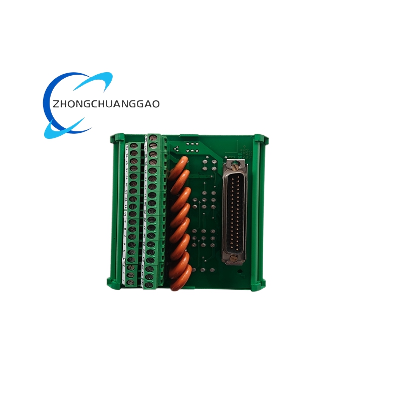
- Rear terminal block array with clearly labeled connections for:
- Generator voltage sensing (L1, L2, L3, N)
- Exciter field output (F+, F−)
- Remote sense inputs (RS+, RS−)
- Analog output (4–20 mA or 0–10 VDC)
- RS-485 communication (A, B)
- Alarm relay output (NO/NC contacts)
- Auxiliary power input (if external supply used)
- Adjustable gain and stability trimmers accessible via front panel (under cover)
- Ventilation slots on top and bottom for natural convection cooling (no fan required)
- Surge protection devices (TVS diodes and MOVs) on all external connections
- EMC shielding via metal enclosure and filtered I/O connections
Working Principle
- The regulator draws self-power from the generator terminals (no external power supply required during normal operation)
- The 3-phase voltage sensing circuit continuously measures the generator output voltage (L1, L2, L3)
- The microprocessor compares the sensed RMS voltage to the user-defined setpoint (adjusted via potentiometer or digital command)
- The error signal (difference between actual and setpoint voltage) is processed by a digital PID control algorithm
- The PID output drives a pulse-width modulated (PWM) exciter field driver, which controls the DC current supplied to the brushless exciter field winding
- The exciter field current adjusts the exciter stator output voltage, which in turn controls the main generator field current via the rotating rectifier assembly
- This closed-loop system maintains the generator terminal voltage at the setpoint regardless of load changes, power factor variations, or speed fluctuations
- Protection circuits monitor for over-voltage, under-voltage, phase loss, and over-excitation conditions, and automatically reduce or cut off excitation to protect the generator
- Stability compensation (gain and phase margin adjustment) ensures the control loop remains stable across all operating conditions, including highly capacitive loads
Advantages and Highlights
- Digital precision: ±1% voltage regulation accuracy, superior to analog regulators (typically ±3–5%)
- Zero drift over time: microprocessor-based control eliminates component aging drift common in analog designs
- Self-powered operation: no external power supply needed — derives power directly from generator terminals
- Wide input voltage range: 120 VAC to 600 VAC line-to-line, covering most industrial generator sizes
- Fast transient response: <50 ms recovery on 100% load steps, minimizing voltage dips
- Built-in communications: RS-485 Modbus RTU enables integration with modern SCADA, BMS, and remote monitoring systems
- Configurable protection: adjustable under/over-voltage thresholds, phase-loss protection, and excitation limiting
- Parallel operation ready: droop compensation enables stable load sharing between multiple generators
- Robust environmental rating: operates from -20°C to +70°C, suitable for harsh industrial and outdoor enclosures
- Long service life: MTBF >100,000 hours, no moving parts, no wear-out components
- Easy commissioning: front-panel potentiometer and LED indicators allow setup without a laptop
- Fault memory: stores last 10 alarm events for troubleshooting
Applicable Industries
| Industry | Application |
|---|---|
| Power Generation | Standby, prime, and continuous diesel/gas generator sets |
| Oil and Gas | Remote well-site power, offshore platform generators |
| Mining | Underground and surface mine backup power systems |
| Marine | Shipboard auxiliary generators, harbor power units |
| Data Centers | Emergency backup generator voltage control |
| Hospitals | Critical care facility backup power |
| Telecommunications | Cell tower and central office backup generators |
| Manufacturing | Factory backup power, cogeneration systems |
| Commercial Buildings | Emergency standby generators for HVAC, lighting, elevators |
| Military / Defense | Field-deployed tactical power systems |
| Renewable Energy | Biogas and biomass generator sets |
| Industrial Plants | Process backup power, black-start capable systems |
Installation Requirements
| Requirement | Specification |
|---|---|
| Mounting | 35 mm standard DIN rail (EN 60715) or panel mount with screws |
| Ambient Temperature | -20°C to +70°C (-4°F to +158°F) |
| Relative Humidity | 5% to 95% non-condensing |
| Altitude | Up to 3000 m (10,000 ft) above sea level (derate above 1000 m) |
| Vibration | <5 g RMS (10–500 Hz), per IEC 60068-2-6 |
| Enclosure IP Rating | IP20 minimum (install in NEMA 1 or higher enclosure for outdoor use) |
| Clearance | Minimum 50 mm above and below for ventilation; 25 mm on sides |
| Cable Sizing (exciter output) | Minimum 2.5 mm² (14 AWG) copper for up to 10 A continuous |
| Cable Sizing (voltage sense) | Minimum 1.5 mm² (16 AWG) copper, shielded recommended |
| Grounding | Chassis ground required; connect to generator frame ground bus |
| Torque on Terminal Screws | 0.8 Nm (7 in-lb) maximum; do not overtighten |
| Electromagnetic Compatibility | Install away from high-current switching devices; maintain 100 mm separation from VFDs |
Usage Precautions
- Never connect the regulator to a live generator without proper wiring verification — incorrect connections will damage the regulator and generator
- Verify phase sequence before energizing — reverse phase sequence will cause the regulator to malfunction and may damage the exciter
- Do not exceed the rated exciter output current of 10 A DC — overloading will destroy the output driver
- Do not bypass the built-in surge protection — external transients will damage the internal circuitry
- Allow 30 seconds warm-up time after initial power-on before expecting accurate regulation
- Do not adjust the internal gain trimmers unless qualified — incorrect settings cause instability and oscillation
- Use shielded cables for voltage sensing in electrically noisy environments to prevent false readings
- Ensure proper ventilation — do not install in a sealed enclosure without airflow; overheating causes thermal shutdown
- Perform annual inspection of terminal connections for tightness and corrosion
- Do not operate the regulator with the front cover removed — exposed terminals carry up to 600 VAC
- When replacing the unit, match the model number exactly — 5437-523 is not interchangeable with 5437-513 without reconfiguration
- Log all fault events using the built-in fault memory or external SCADA for preventive maintenance
- Do not use the regulator with generators exceeding 600 VAC line-to-line — this will destroy the input sensing circuit
- For parallel operation, configure droop setting on all units identically — mismatched droop causes circulating currents and instability
- Store spare units in a dry, temperature-controlled environment (0°C to 40°C, <70% RH)
Software and Configuration
| Tool | Function |
|---|---|
| Woodward TOOLBOX Software | PC-based configuration via RS-485; adjust setpoint, gain, bandwidth, droop, alarm thresholds |
| Woodward 5437 Configurator | Web-based setup utility for quick commissioning |
| Modbus RTU Registers | Standard register map for third-party SCADA integration |
| Analog Output Scaling | Configurable 4–20 mA or 0–10 VDC proportional to terminal voltage |
Key Parameters Summary (Bold Reference)
| Field | Value |
|---|---|
| Product Name | Woodward 5437-523 Digital AVR |
| Regulator Type | Digital, microprocessor-based AVR |
| Sensing | 3-phase, 120–600 VAC |
| Frequency Range | 45 Hz to 65 Hz |
| Exciter Output Current | 0 to 10 A DC continuous |
| Exciter Output Voltage | 0 to 300 VDC maximum |
| Voltage Accuracy | ±1% of setpoint |
| Transient Response | <50 ms (100% load step) |
| Operating Temp | -20°C to +70°C |
| Communication | RS-485 Modbus RTU |
| Mounting | 35 mm DIN rail |
| MTBF | >100,000 hours |
| Certifications | UL 508, CE, CSA, IEC 61000 |
Reviews
There are no reviews yet.