
Product Short Description
Product Overview
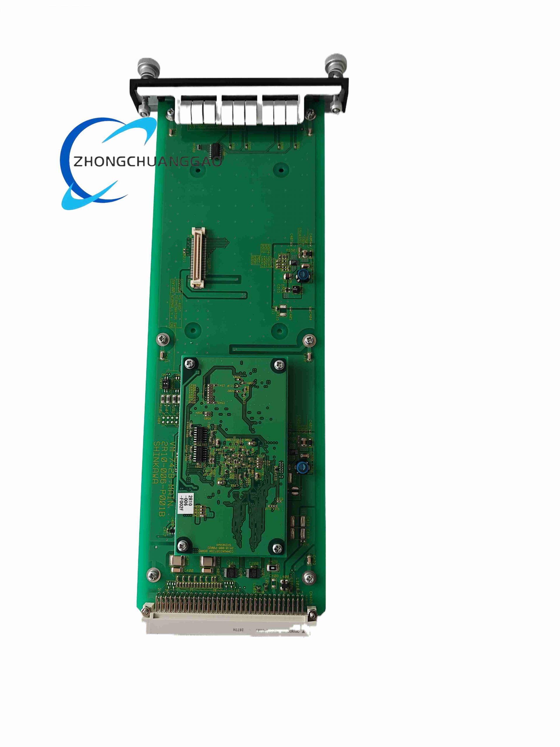
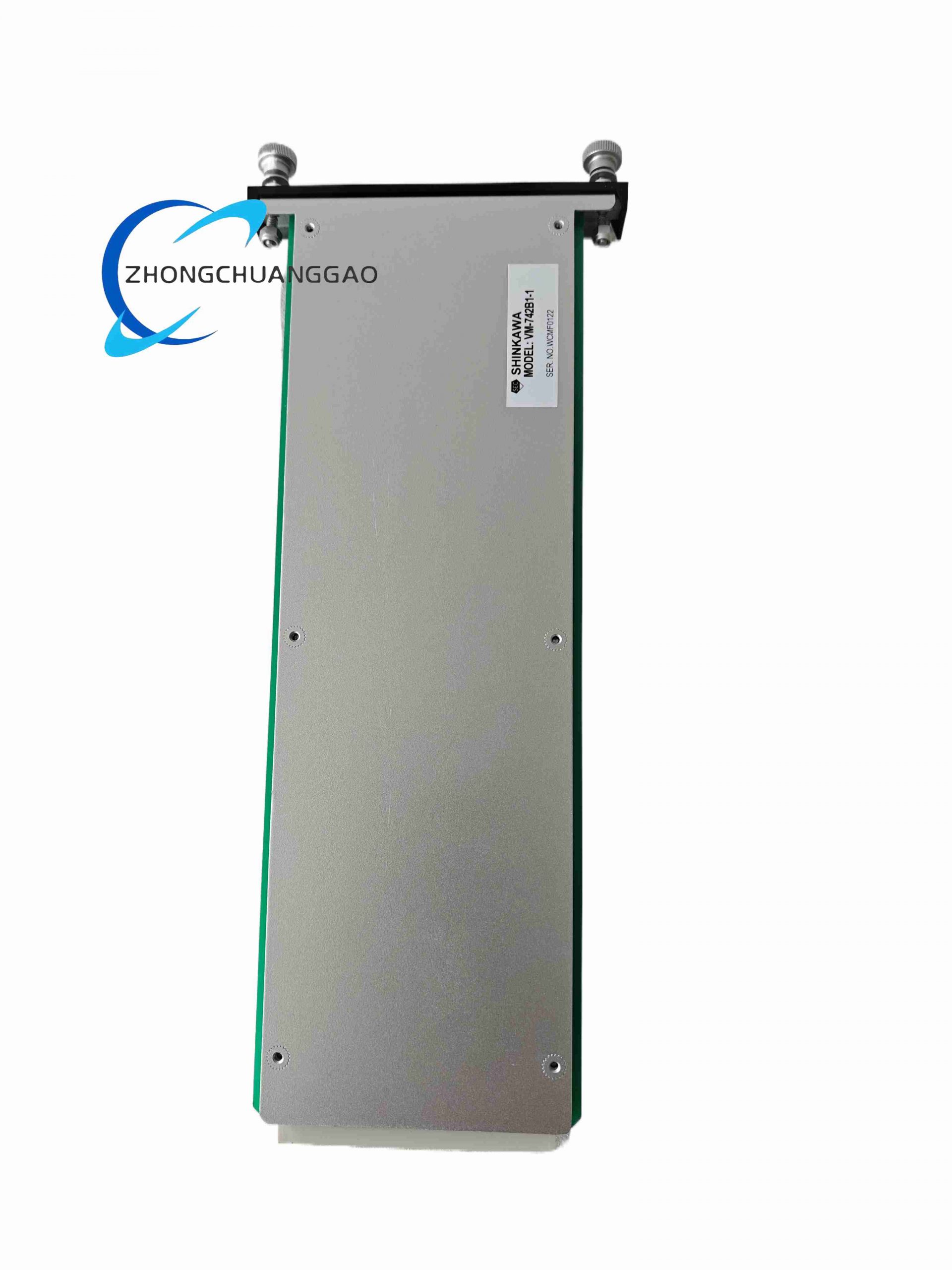
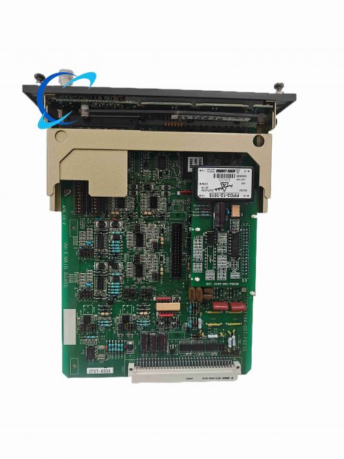
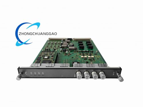
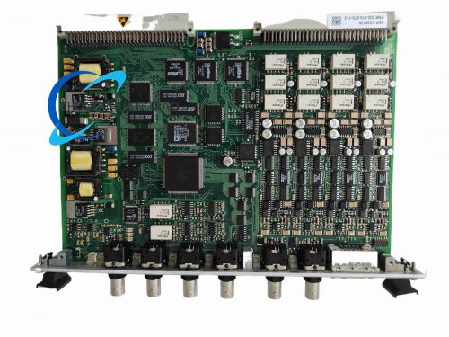
VM-742B1-1 is single-channel dedicated signal conditioning module for eddy current proximity probes, designed to convert weak probe impedance variation signals into standardized linear analog voltage outputs for machinery shaft displacement monitoring. It matches all Meggitt Vibro-Meter series proximity transducers and integrates built-in probe fault detection circuit for cable breakage, short-circuit and target metal surface abnormality diagnosis. Widely deployed as front-end signal pre-amplifier for turbine and compressor shaft vibration measurement systems.
Description
Core Technical Specifications
- Channel Configuration: Single independent eddy-current transducer input channel
- Probe Excitation Output: -22 VDC constant regulated excitation current source
- Linear Measuring Range: 0~2 mm shaft-probe clearance standard range
- Output Signal Standard: 0~10 VDC linear analog output (1 V = 0.2 mm clearance)
- Signal Bandwidth: DC ~ 12 kHz flat frequency response
- Fault Detection Logic: Automatically identifies probe open circuit, short circuit, target material mismatch
- Fault Output: Isolated transistor switch fault alarm signal
- Operating Power Supply: 24 VDC ±10% rack power input, power consumption ≤3 W
- Operating Temperature Range: -10°C ~ +75°C
- Mounting Format: Compact 1U single-slot 19-inch rack module
- Linearity Error: ≤0.15% full scale measurement deviation
- Transducer Cable Compatibility: Supports up to 100 m length standard coaxial probe cables
Functional Features
- Single-channel dedicated eddy current signal amplification with ultra-low noise analog circuit design, minimum signal distortion for micro-clearance shaft measurement
- Real-time transducer health diagnostic function; automatically trigger fault output if probe cable breaks or shorts
- Adjustable gain trim potentiometer on front panel for calibration matching different probe model linear ranges
- Wide DC-to-high-frequency bandwidth covers static shaft position and dynamic rotating vibration signals simultaneously
- Optoelectronic isolation between field transducer circuit and back-end acquisition system to eliminate ground loop interference
- Compact 1U rack footprint allows dense multi-channel system layout for multi-bearing monitoring racks
- Short-circuit protection on excitation output; automatic current limiting prevents permanent module damage during cable short-circuit faults
Working Principle
Internal oscillator generates high-frequency alternating excitation signal supplied to eddy current probe coil. Probe coil magnetic field interacts with conductive rotating shaft surface, generating eddy current feedback that changes coil impedance. VM-742B1-1 analog front-end circuit detects tiny impedance fluctuations, amplifies and linearizes the signal via precision op-amp circuits, then outputs standardized 0~10 VDC analog voltage proportional to shaft clearance distance. Simultaneous auxiliary monitoring circuit tracks excitation current magnitude; abnormal current levels trigger fault transistor output to notify host monitoring system of transducer failure.
Material & Structural Characteristics
- Circuit Board: Low-noise FR4 PCB with gold-plated signal trace surface to reduce signal attenuation
- Front Panel: Black anodized aluminum with sealed trim potentiometer access port rubber cap
- Transducer Interface: Sealed BNC coaxial connector for probe cable connection
- Analog Output Terminals: Screw-locking copper terminal block for 0~10 VDC signal wiring
- Internal Components: Low-temperature drift precision operational amplifiers, metal foil fixed resistors for stable linearity
- Housing Frame: Cold-rolled steel bending frame with anti-vibration rubber shock absorption pads
Installation Requirements
- Mount VM-742B1-1 module within 50 m maximum distance from target eddy current probe to minimize coaxial signal loss
- Separate probe coaxial cables from AC power cables with minimum 20 cm horizontal separation in cable trays
- Rack power supply input wiring uses twisted pair shielded cable with shield grounded at cabinet earth bar only
- Reserve minimum 0.5 slot empty space between multiple VM-742 modules for heat dissipation in dense rack layouts
- BNC connector dust caps must remain installed when probe cable is disconnected to prevent PCB contamination
- Cabinet forced air cooling required if continuous operating ambient temperature exceeds 65°C
Application Scenarios
- Steam/gas turbine radial shaft vibration and thrust bearing axial displacement front-end signal conditioning
- Centrifugal compressor rotor eccentricity, shaft float continuous monitoring pre-amplification
- Generator large rotating shaft relative vibration measurement signal conversion
- Industrial high-speed gearbox shaft clearance safety monitoring systems
- Hydropower turbine main shaft bearing position abnormal early detection
Operation & Maintenance Precautions
- Do not adjust front-panel gain potentiometer without certified calibration equipment; misadjustment causes severe linear measurement error
- Inspect BNC connector coaxial cable shielding integrity quarterly; cracked shielding induces high-frequency noise distortion
- If fault alarm activates, sequentially check probe tip wear, cable breakage and shaft target surface corrosion before module replacement
- Avoid mounting module near high-current contactors and variable frequency drives to suppress electromagnetic interference
- Perform linearity calibration every 18 months using certified eddy current static calibration fixture
- Never connect excitation output terminal to ground; short-circuit triggers automatic current limiting and temporary measurement shutdown
Reviews
There are no reviews yet.