
Product Short Description
Product Brief
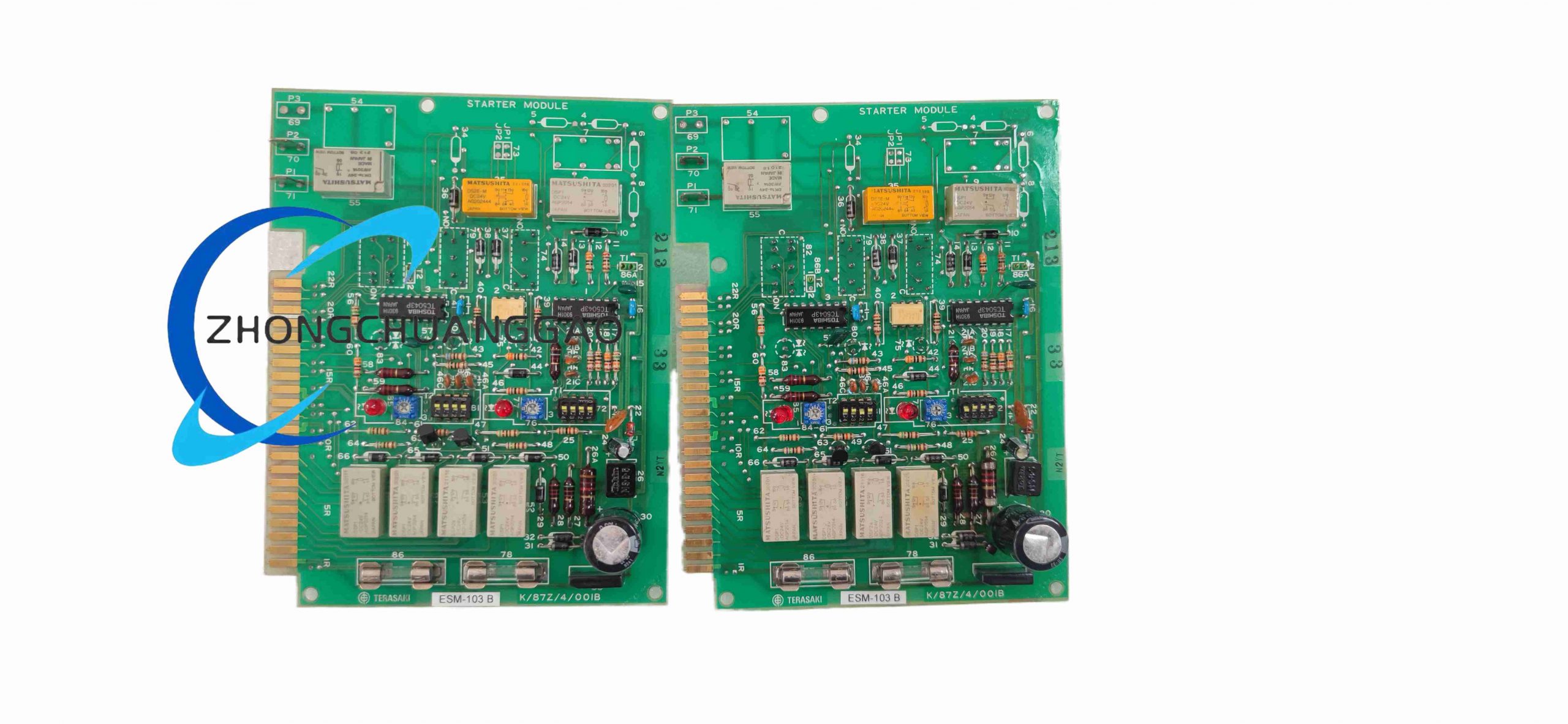
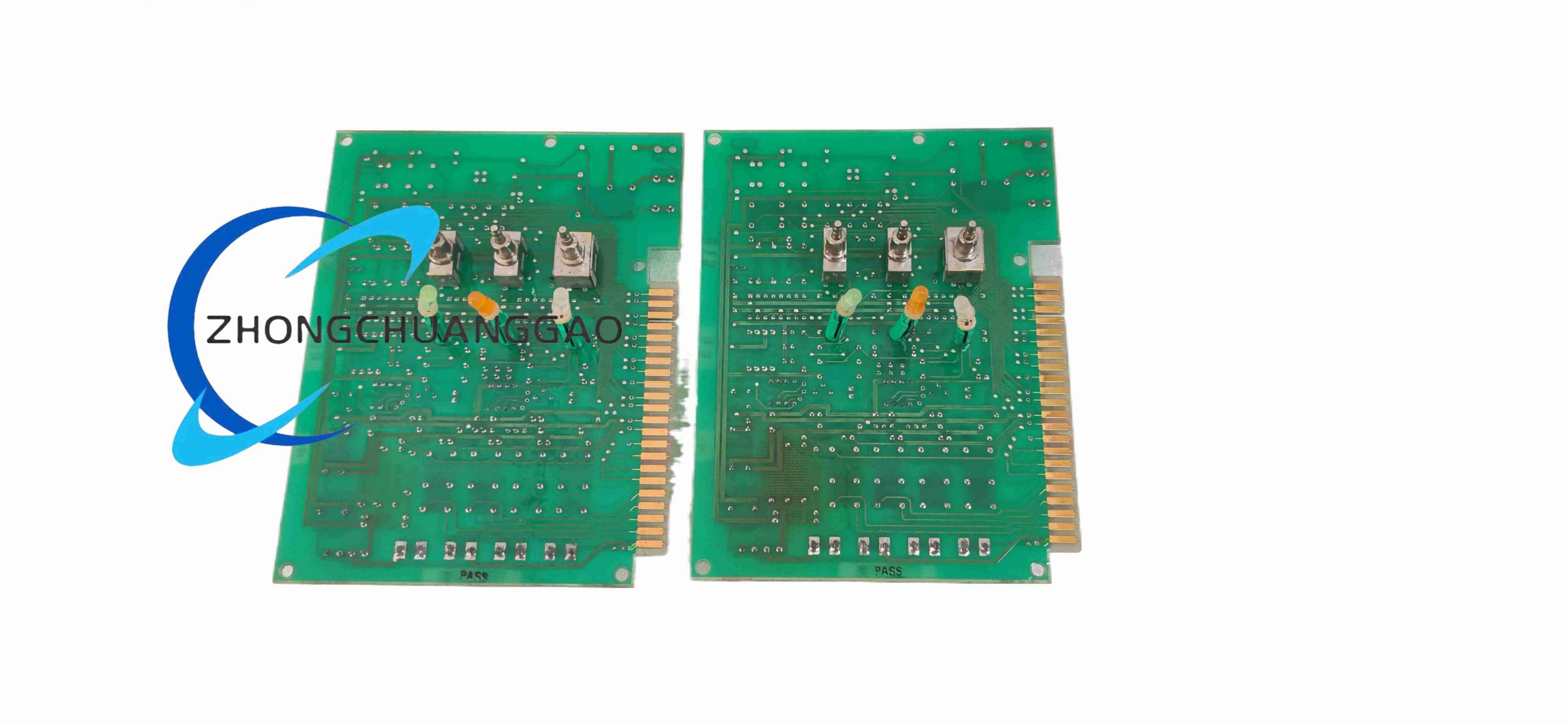
ESM-103B is a microprocessor-controlled multi-function motor protection relay developed exclusively for marine low-voltage three-phase induction motors, integrating overload, short-circuit, phase loss, phase unbalance and earth fault detection for vessel auxiliary machinery motors.
Model Series
ESM Marine Motor Protection Relay Series, model ESM-103B three-phase comprehensive protection variant
Description
Technical Specifications
- Auxiliary Control Supply Voltage: AC 110 V / 220 V dual rated 50/60 Hz
- Motor Current Monitoring Range: 0.5 A – 100 A via matched Terasaki CTs
- Protection Function Thresholds Configurable: Overload, locked rotor, phase loss, phase unbalance, earth leakage
- Output Relay Contacts: 1 trip contact, 2 independent alarm auxiliary contacts; 6 A / 250 VAC resistive rating
- Communication Interface: RS485 Modbus RTU for remote monitoring data transmission
- Operating Temperature: -10 °C to +55 °C
- Certifications: IEC 60945, DNV, LR, NK marine classification standards compliant
Functional Features
- Digital thermal memory overload protection simulating motor winding thermal accumulation
- Instantaneous short-circuit trip function with adjustable short-circuit current threshold
- Phase loss and three-phase current unbalance detection with configurable trip delay timer
- Zero-sequence CT earth fault leakage protection circuit for motor winding insulation failure
- Front panel digital 4-digit LED display for real-time three-phase current reading and fault code indication
- Modbus RTU communication for remote SCADA vessel monitoring system integration
- Front panel manual test button simulates all fault conditions to verify protection circuit operation
- Latched fault memory storage retaining last 8 motor fault event records with timestamp
Performance Parameters
- Overload thermal trip accuracy: ± 3% of user-configured current threshold
- Short-circuit trip response time: ≤ 60 ms at 10× rated motor current
- Phase unbalance detection sensitivity: Minimum 10% current deviation between phases
- Fault event memory data retention: 10 years non-volatile memory storage
Material Composition
- Main housing enclosure: Flame retardant V0 ABS plastic marine anti-salt corrosion formulation
- Internal PCB: FR4 high-temperature printed circuit board with salt-fog resistant conformal coating
- Current measurement transformers: Silicon steel laminated miniature current sensors integrated on PCB
- Terminal blocks: Tin-plated copper conductive terminals with PA66 flame retardant plastic housing
Structural Characteristics
- Standard 35 mm DIN rail mounting housing, width 90 mm, height 110 mm, depth 125 mm
- Front panel dedicated LED display, navigation setting buttons and test pushbutton
- Rear terminal block partitioned into control supply, CT signal, relay output and communication wiring zones
- Integrated locking DIN rail clip for vibration-resistant marine cabinet installation
Working Principle
Three-phase motor current signals captured by external current transformers are converted to low-level secondary signals sampled by the ESM-103B internal measurement circuit. On-board microprocessor continuously calculates thermal load accumulation, phase current balance and residual earth leakage values against user-programmed protection thresholds. When any parameter exceeds safe operating limits, corresponding output relay energizes to trigger motor circuit breaker trip or activate remote alarm annunciators. All fault events are timestamped and stored in non-volatile flash memory, while real-time motor current data is broadcast via RS485 Modbus RTU bus to vessel central monitoring systems. Front panel test button injects simulated fault signals to validate full protection chain functionality without motor energization.
Advantage Highlights
- Complete multi-function motor protection eliminating requirement for multiple discrete marine relays
- Marine-specific conformal PCB coating withstands vessel salt-fog corrosive atmospheric conditions
- Digital thermal memory accurately replicates motor winding heat accumulation during intermittent cycling loads
- Built-in Modbus communication natively compatible with SAM Electronics EMP series marine alarm systems
- DIN rail compact form factor optimized for Terasaki marine main and auxiliary switchboard cabinets
- Eight-event fault log provides comprehensive diagnostic data for marine machinery failure root cause analysis
Applicable Industries
Commercial ocean vessels, offshore support platforms, naval auxiliary craft, refrigeration compressor motors, ballast pump motors, ventilation fan motors, hydraulic pump motors, fire pump marine motor control centers
Installation Requirements
- Mount unit inside climate-controlled marine electrical cabinet with maximum relative humidity 90% non-condensing
- Route CT secondary wiring as twisted shielded cable with maximum total run length 20 m
- Maintain minimum 10 cm separation between CT signal wiring and high-power three-phase motor cables
- Connect RS485 Modbus bus wiring in daisy-chain topology with 120 Ω termination resistor at bus endpoints
- Secure unit fully locked to DIN rail to resist marine machinery vibration
- Earth unit housing to vessel protective ground bus via minimum 2.5 mm² copper conductor
Operation Precautions
- Execute full protection function test via front panel button prior to vessel sea trial commissioning
- Download and archive fault event log data after every motor protection trip occurrence
- Calibrate CT current matching parameters whenever connected motor rated power is modified
- Avoid installation in compartments subject to continuous saltwater spray without secondary sealed cabinet housing
- Disconnect auxiliary AC supply voltage before modifying internal wiring terminal connections
- Clear fault memory logs only after completing vessel machinery inspection documentation
Reviews
There are no reviews yet.