
Product Short Description
Product Brief
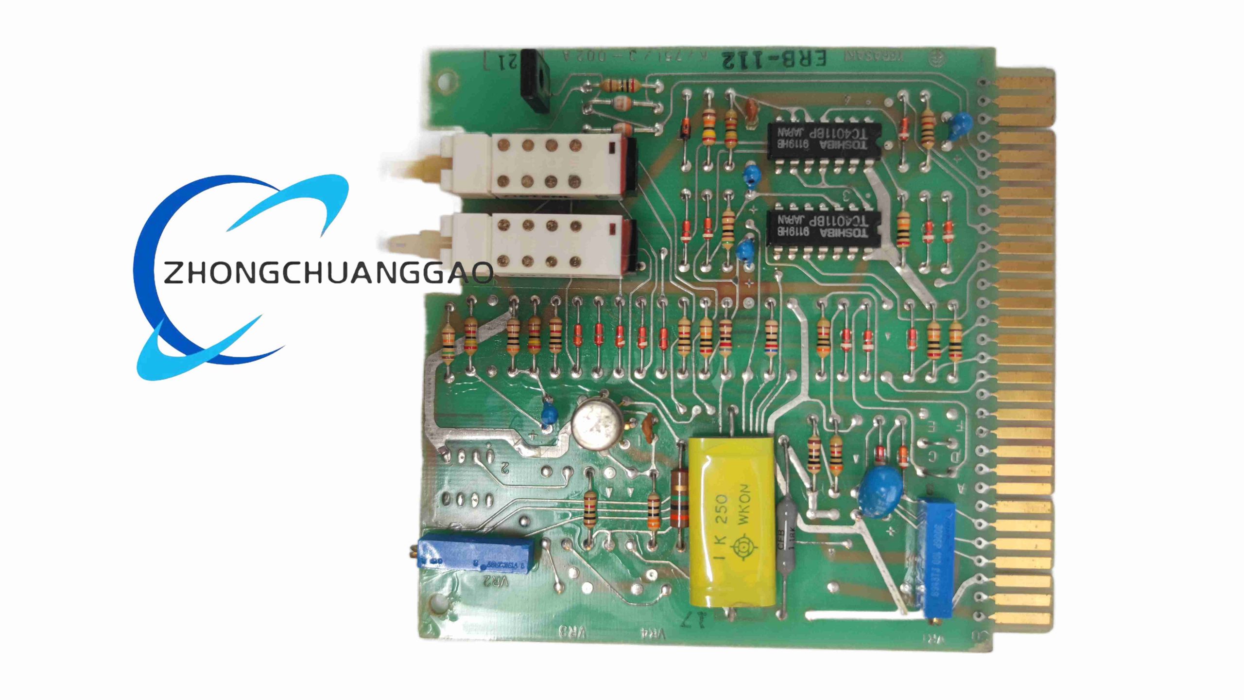
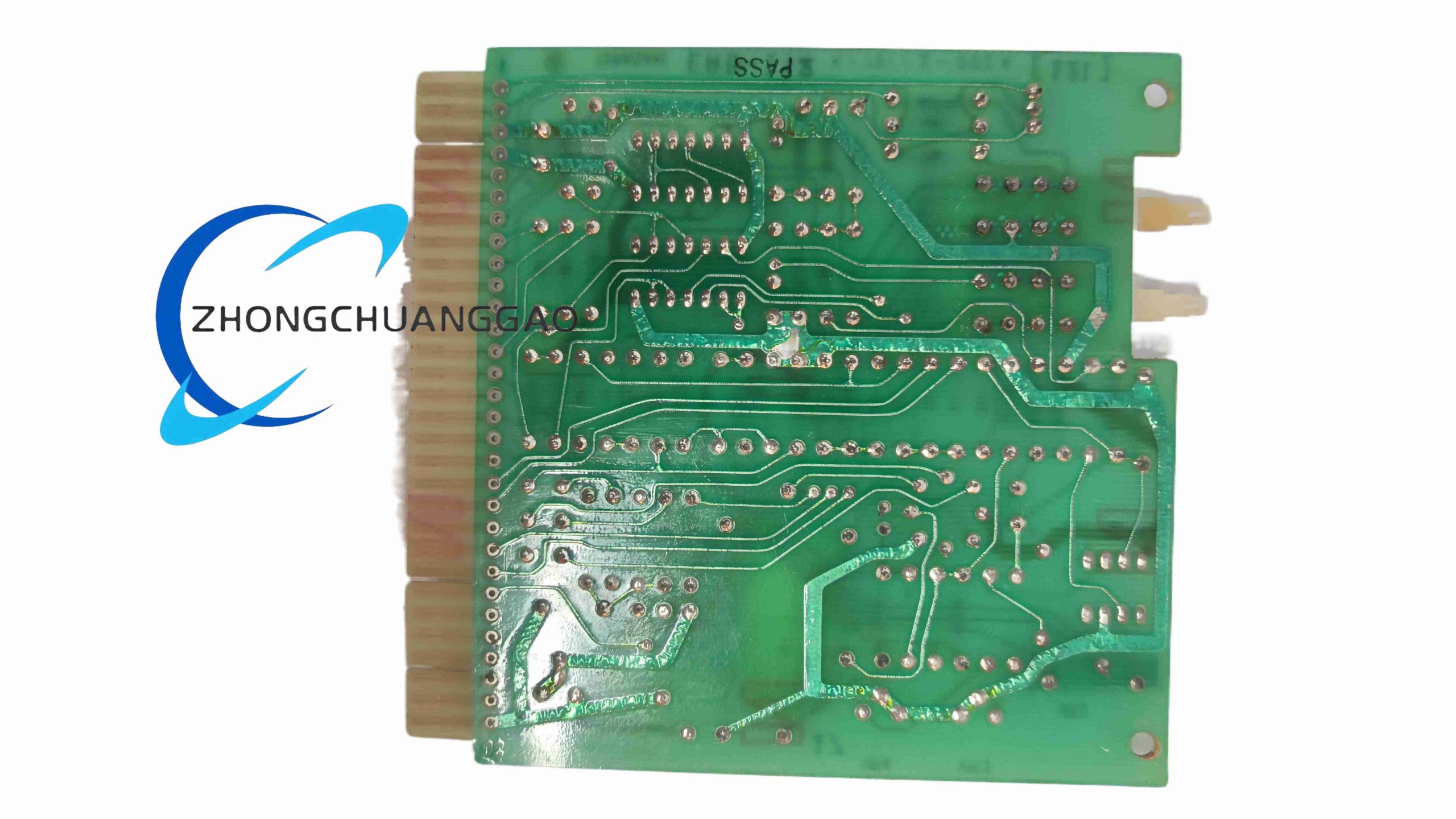
ERB-112 is a dedicated marine-grade residual current earth fault protection relay manufactured by Terasaki Electric, designed for AC low-voltage marine distribution switchboards to detect insulation breakdown and earth leakage faults in vessel power circuits.
Model Series
ERB Series Marine Earth Fault Protection Relays, model ERB-112 single-circuit fixed setting variant
Description
Technical Specifications
- Rated Supply Voltage: AC 100 V / 220 V 50/60 Hz dual supply compatible
- Earth Fault Trip Current Fixed Setting: 12 A residual leakage current threshold
- Operating Trip Time: Instantaneous trip ≤ 80 ms at 1.5× rated fault current
- Auxiliary Output Contacts: 2 SPST alarm/trip relay contacts, 5 A / 250 VAC contact rating
- Compatible CT Ratio: 300/5, 500/5, 800/5 marine zero-sequence current transformers
- Operating Ambient Temperature: -10 °C to +50 °C
- Protection Enclosure Class: IP30 front panel
- Compliance Standards: IEC 60945 marine electrical standard, NK, DNV, ABS marine classification certified
Functional Features
- Zero-sequence current transformer signal sampling for three-phase earth leakage detection
- Fixed 12 A leakage trip threshold optimized for medium-capacity marine distribution feeders
- Dual independent relay output contacts: one circuit breaker trip signal, one remote fault alarm signal
- Built-in power supply surge suppression circuit for unstable marine grid voltage fluctuations
- Internal fault self-test circuit activated via front panel manual test pushbutton
- Red LED front panel fault indication latched upon earth fault detection
- Manual reset pushbutton to clear latched fault indication post-fault clearance
Performance Parameters
- Minimum detectable leakage current: 20% of fixed 12 A trip setting
- Contact mechanical service life: 5,000,000 switching cycles under rated resistive load
- Signal circuit insulation withstand voltage: 2 kV AC 1 minute dielectric strength
- Fault indication latch retention: Permanent until manual reset trigger
Material Composition
- Front panel housing: Flame retardant ABS V0 grade plastic with UV anti-degradation coating
- Internal circuit PCB: FR4 flame retardant printed circuit board
- Electromagnetic relay cores: Silicon steel laminated low-loss magnetic material
- Terminal block components: Glass fiber reinforced PA66 plastic, tin-plated copper terminals
Structural Characteristics
- Standard DIN rail mounting form factor, width 72 mm, height 90 mm, depth 110 mm
- Front panel integrated test button, reset button, red fault indicator LED
- Separate terminal wiring zones for supply voltage, CT secondary signal and relay output circuits
- Fully enclosed internal circuit chamber isolated from external wiring compartment
Working Principle
Zero-sequence current transformer installed around three-phase feeder cables outputs secondary proportional current corresponding to total circuit earth leakage. The ERB-112 internal electromagnetic comparator circuit measures residual current magnitude; when leakage exceeds fixed 12 A threshold, internal actuation coil energizes dual output relays. One relay sends trip signal to upstream molded case circuit breaker, while the second relay activates remote onboard alarm panels. Fault detection latches front panel red LED indicator until operator depresses manual reset pushbutton. Front test button injects simulated leakage signal to verify full protection circuit functionality without inducing real power system faults.
Advantage Highlights
- Full global marine classification society certification for shipboard low-voltage distribution systems
- Fixed 12 A trip threshold eliminates parameter configuration errors during vessel commissioning
- Dual relay output architecture separates circuit breaker tripping and remote alarm signaling
- Compact DIN rail mount design for seamless integration into Terasaki marine main switchboards
- Internal surge filtering withstands voltage transients generated by marine propulsion converters
- Simple manual self-test function enables regular protection circuit verification per marine safety regulations
Applicable Industries
Ocean-going cargo ships, passenger vessels, offshore wind service vessels, floating offshore platforms, coastal fishing vessels, marine electrical distribution panel manufacturing
Installation Requirements
- Mount unit inside marine main switchboard cabinet with non-condensing humidity ambient conditions
- Route zero-sequence CT secondary wiring as twisted shielded pair with maximum cable length 15 m
- Isolate CT signal wiring from high-current three-phase power cables by minimum 8 cm separation distance
- Connect dedicated filtered AC supply circuit to avoid supply voltage distortion interference
- Secure unit firmly to standard 35 mm DIN mounting rail with locking clip
- Earth unit cabinet housing to vessel protective ground bus via 2.5 mm² copper wire
Operation Precautions
- Do not modify internal circuit components to alter fixed 12 A leakage trip threshold
- Conduct full self-test verification monthly per marine electrical safety operational procedures
- Replace unit immediately if front panel LED fails to illuminate during manual self-test procedure
- Prevent CT secondary circuit open-circuit condition during maintenance to eliminate dangerous high induced voltage
- Avoid installation in compartments with continuous saltwater mist exposure without additional sealed cabinet housing
- Disconnect auxiliary supply voltage before performing internal wiring modification work

-500x500.jpg)

Reviews
There are no reviews yet.