Product Short Description
Product Introduction:
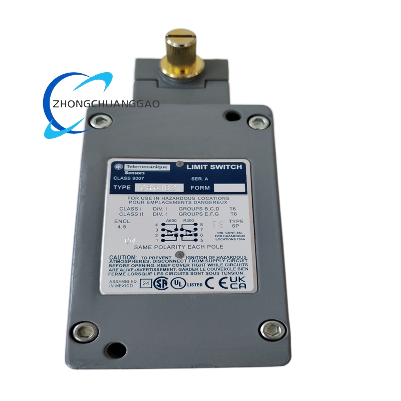
The Telemecanique 9007CR61B2 is a single-pole double-throw (SPDT) control relay from the 9007CR series within the TeSys D control relay family. It is a compact DIN rail-mountable relay intended for low-power switching applications in control circuits. The model code 9007CR61B2 decodes as follows: 9007 = TeSys D control relay series, C = control relay function, R = relay output type (SPDT), 61 = 6 A rated current at AC-15, B2 = 24 VDC coil voltage. The relay features 1 changeover contact (1 NO + 1 NC) and is rated for 6 A at 250 VAC for resistive loads.
Description
Technical Specifications:
- Model Number: 9007CR61B2
- Manufacturer: Telemecanique (Schneider Electric)
- Series: TeSys D (9007CR)
- Relay Type: Miniature Control Relay (DIN Rail Mount)
- Contact Configuration: 1 SPDT (1 NO + 1 NC)
- Coil Voltage: 24 VDC
- Coil Power Consumption: 0.7 W (hold) / 1.5 W (pull-in)
- Contact Rating (AC-15): 6 A at 250 VAC
- Contact Rating (DC-13): 5 A at 24 VDC
- Contact Rating (Resistive Load): 10 A at 250 VAC (AC-1)
- Mechanical Life: 10,000,000 operations
- Electrical Life (AC-15): 300,000 operations at 6 A, 250 VAC
- Contact Material: Silver Nickel (AgNi) alloy
- Insulation Class: Class B (130°C)
- Protection Rating: IP20 (finger-safe, indoor use only)
- Mounting: DIN rail (EN 60715, 35 mm)
- Operating Temperature: -25°C to +70°C (-13°F to +158°F)
- Storage Temperature: -40°C to +85°C (-40°F to +185°F)
- Humidity: 5% to 95% (non-condensing)
- Vibration: 5 g, 10–55 Hz (per IEC 60068-2-6)
- Shock: 50 g, 11 ms half-sine (per IEC 60068-2-27)
Functional Features:
- 1 Changeover Contact (SPDT): Provides 1 normally open (NO) and 1 normally closed (NC) contact for switching two independent circuits
- 24 VDC Coil: Operates on 24 VDC nominal with a wide operating range of 19.2 VDC to 28.8 VDC (80% to 120% of rated voltage)
- LED Status Indicator: Built-in red LED on the front panel indicates coil energization status
- DIN Rail Mounting: Snap-on mounting to standard 35 mm top-hat DIN rail (EN 60715)
- Quick-Connect Terminals: Screwless push-in terminals for fast wiring without tools
- Socket Base Compatible: Fits RXM socket base (947-30) for plug-in relay replacement without rewiring
- LED Indicator: Visual coil status indication from the front of the panel
- Wide Operating Voltage Range: Functions reliably from 19.2 VDC to 28.8 VDC; tolerates voltage fluctuations in industrial DC power supplies
- Silent Operation: No audible click during switching; suitable for noise-sensitive environments
- Polarity Insensitive Coil: DC coil operates regardless of wire polarity (non-polarized)
Performance Parameters:
| Parameter | Value |
|---|---|
| Model Number | 9007CR61B2 |
| Coil Voltage | 24 VDC (19.2–28.8 VDC range) |
| Coil Power (Hold) | 0.7 W |
| Coil Power (Pull-in) | 1.5 W |
| Contact Configuration | 1 SPDT (1 NO + 1 NC) |
| Contact Rating (AC-15) | 6 A at 250 VAC |
| Contact Rating (DC-13) | 5 A at 24 VDC |
| Contact Rating (AC-1) | 10 A at 250 VAC (resistive) |
| Contact Material | Silver Nickel (AgNi) |
| Mechanical Life | 10,000,000 operations |
| Electrical Life (AC-15) | 300,000 operations at 6 A, 250 VAC |
| Insulation Class | Class B (130°C) |
| Protection Rating | IP20 |
| Mounting | 35 mm DIN rail (EN 60715) |
| Operating Temperature | -25°C to +70°C |
| Storage Temperature | -40°C to +85°C |
| Vibration | 5 g, 10–55 Hz |
| Shock | 50 g, 11 ms half-sine |
| Dimensions (W×H×D) | Approximately 18 × 74 × 63 mm (0.71 × 2.91 × 2.48 in) |
| Weight | Approximately 40 g (0.09 lbs) |
| Terminal Type | Push-in (screwless) |
| LED Indicator | Red (coil energized) |
| Compliance | UL 508, CSA C22.2 No. 14, IEC 61812-1, EN 60947-5-1 |
| Listing | UL Listed, CSA Certified, CE Marked |
Material Composition:
- Housing: UL 94V-0 rated flame-retardant polycarbonate (PC) blend (light gray)
- Contact Arms: Silver Nickel (AgNi 15) alloy for low contact resistance and high welding resistance
- Contact Springs: Beryllium copper (BeCu) alloy with gold flash plating for corrosion resistance
- Coil Bobbin: Glass-filled nylon (PA66-GF30) for thermal stability
- Coil Windings: Copper magnet wire with Class B (130°C) polyesterimide enamel insulation
- Terminal Blocks: Tin-plated phosphor bronze with spring-loaded push-in mechanism
- LED Lens: Clear polycarbonate with red diffusing pigment
- DIN Rail Clip: Zinc-plated spring steel with locking tab
- Internal Wiring: 22 AWG stranded tinned copper with PVC insulation
- Nameplate: Laser-etched polycarbonate label with model number and ratings
Structural Features:
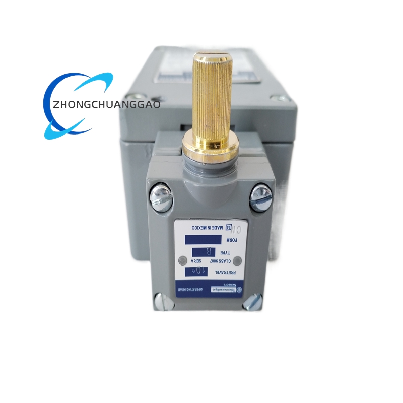
- Ultra-Compact Design: 18 mm wide housing fits in tight DIN rail panels with limited space
- DIN Rail Mounting: Snap-on clip mounts to standard 35 mm top-hat rail (EN 60715); release lever for quick removal
- Front Panel: Red LED indicator (top), push-in terminal openings (bottom), model number label (center)
- Rear Panel: DIN rail clip mechanism, coil terminals (A1, A2), contact terminals (13, 14, 24)
- Terminal Layout: A1/A2 = coil terminals (top); 13 (COM), 14 (NC), 24 (NO) = contact terminals (bottom); push-in wire insertion from front
- Socket Compatibility: Fits RXM4 socket base (947-30); relay slides into socket for tool-free replacement
- LED Position: Top-front; visible through panel cutout for remote status monitoring
- Ventilation: Molded ventilation slots on sides for passive cooling of coil
- Polarity Marking: A1 (+) and A2 (−) marked on coil terminals; non-polarized operation
Working Principle:
The Telemecanique 9007CR61B2 operates on the principle of electromagnetic actuation. When 24 VDC is applied across the coil terminals (A1 and A2), current flows through the copper magnet windings wound on a glass-filled nylon bobbin around a laminated silicon steel armature. The energized coil generates a magnetic field that pulls the armature toward the fixed core, overcoming the return spring force. The armature is mechanically linked to the contact lever assembly, which pivots the movable contact (COM, terminal 13) from the normally closed (NC, terminal 14) position to the normally open (NO, terminal 24) position. When coil power is removed, the return spring pushes the armature back, returning the contact to the NC position. The Silver Nickel (AgNi) contacts provide low-resistance switching with high resistance to welding under inductive loads. The red LED is wired in parallel with the coil (via an internal current-limiting resistor) and illuminates when the coil is energized, providing visual status indication. The relay switches within 10 ms (pull-in time) and 5 ms (drop-out time).
Advantages and Highlights:
- Ultra-Compact 18 mm Width: Saves panel space; fits in density-critical DIN rail installations
- 10,000,000 Mechanical Operations: Extremely long mechanical life for high-cycle switching applications
- 300,000 Electrical Operations at 6 A: Rated for 300,000 cycles at full load (AC-15) before contact replacement
- 6 A at 250 VAC (AC-15): Handles inductive loads (solenoids, contactors, relays) at full rated current
- Socket Base Compatible (RXM4): Tool-free relay replacement; swap relays without disconnecting wiring
- Push-In Terminals: Screwless wiring speeds up installation and reduces wiring time by 50%
- Wide Voltage Range (19.2–28.8 VDC): Tolerates ±20% voltage fluctuation without malfunction
- LED Status Indicator: Front-panel visual feedback for coil energization without opening the panel
- Silent Operation: No audible click; suitable for office, hospital, and residential environments
- Non-Polarized Coil: DC coil works with either polarity; eliminates wiring errors
- UL 508 Listed / CSA Certified / CE Marked: Approved for North American and European industrial markets
- Telemecanique Legacy: Fully compatible with legacy Telemecanique and Square D control relay systems
Applicable Industries:
- Industrial Automation: PLC output expansion, auxiliary circuit switching, interlocking logic
- Machine Control: Solenoid valve actuation, indicator lamp control, safety interlock circuits
- HVAC and Building Automation: Damper control, fan sequencing, chiller auxiliary circuits
- Process Control: Valve actuation, pump start/stop sequencing, alarm circuit switching
- Material Handling: Conveyor interlocking, hoist control, gate sequencing
- Packaging Machinery: Cutter actuation, labeler control, filler valve switching
- Textile Machinery: Yarn feeder control, loom auxiliary circuits, winding machine logic
- Food and Beverage: Mixer control, valve actuation, conveyor interlocks
- Water and Wastewater: Pump control, valve sequencing, alarm circuit switching
- Energy Management: Transformer cooling control, capacitor bank switching, UPS auxiliary circuits
Model Series:
| Model Number | Coil Voltage | Contact Rating (AC-15) | Contacts | Description |
|---|---|---|---|---|
| 9007CR11B2 | 24 VDC | 6 A at 250 VAC | 1 SPDT (1 NO + 1 NC) | Standard 24 VDC control relay (current model) |
| 9007CR21B2 | 48 VDC | 6 A at 250 VAC | 1 SPDT (1 NO + 1 NC) | 48 VDC coil variant |
| 9007CR31B2 | 110 VDC | 6 A at 250 VAC | 1 SPDT (1 NO + 1 NC) | 110 VDC coil variant |
| 9007CR41B2 | 230 VDC | 6 A at 250 VAC | 1 SPDT (1 NO + 1 NC) | 230 VDC coil variant |
| 9007CR51B2 | 24 VAC | 6 A at 250 VAC | 1 SPDT (1 NO + 1 NC) | 24 VAC coil variant |
| 9007CR61B2 | 24 VDC | 6 A at 250 VAC | 1 SPDT (1 NO + 1 NC) | 24 VDC, 6 A rated (current model) |
| 9007CR71B2 | 120 VAC | 6 A at 250 VAC | 1 SPDT (1 NO + 1 NC) | 120 VAC coil variant |
| 9007CR81B2 | 230 VAC | 6 A at 250 VAC | 1 SPDT (1 NO + 1 NC) | 230 VAC coil variant |
| 9007CR21M7 | 24 VDC | 16 A at 250 VAC | 2 SPDT (2 NO + 2 NC) | 24 VDC, 16 A high-current variant |
| 9007CR41M7 | 230 VDC | 16 A at 250 VAC | 2 SPDT (2 NO + 2 NC) | 230 VDC, 16 A high-current variant |
| 9007CR61M7 | 24 VDC | 16 A at 250 VAC | 2 SPDT (2 NO + 2 NC) | 24 VDC, 16 A high-current variant |
| 9007CR61F7 | 24 VDC | 6 A at 250 VAC | 1 SPDT (1 NO + 1 NC) | Socket base (RXM4) compatible variant |
Installation Requirements:
- Mounting Surface: Standard 35 mm DIN rail (EN 60715, top-hat profile) in a control panel or dedicated enclosure
- Enclosure Rating: Minimum NEMA 1 (indoor) or IP20; use NEMA 4X (outdoor/washdown) if installed outside
- Ambient Temperature: Maintain enclosure interior at -25°C to +55°C for optimal contact life
- Clearance: Minimum 15 mm (0.6 in) clearance above and below relay for ventilation
- Power Supply: 24 VDC regulated; maximum ripple <5% of rated voltage (1.2 VDC peak-to-peak)
- Grounding: Connect chassis ground to building equipment grounding conductor; ground resistance <1 Ω
- Cable Routing: Separate signal cables (coil, contacts) from power cables (24 VDC supply) by minimum 50 mm (2 in)
- Wire Gauge: Use 18–22 AWG stranded copper wire for coil and contact circuits; 14–18 AWG for 24 VDC power feed
- Terminal Connection: Insert wire fully into push-in terminal until it clicks; do not use screwdriver
- DIN Rail Torque: Snap relay onto rail until locking tab engages; pull release lever to remove
- Socket Installation (Optional): Mount RXM4 socket base (947-30) on DIN rail first; slide relay into socket
- Coil Wiring: Connect 24 VDC to A1 (+) and A2 (−); polarity does not matter
- Contact Wiring: Connect load circuit to COM (13) and NO (24) for energized-on operation; use NC (14) for energized-off operation
- Bus Termination: Not applicable (discrete relay; no bus termination required)
Usage Precautions:
- Do not exceed 28.8 VDC coil voltage: Overvoltage above 120% of rated voltage (28.8 VDC) damages coil insulation permanently
- Do not reverse polarity on AC coil variants: 24 VAC, 120 VAC, 230 VAC coils are polarity-sensitive; connect correctly
- Do not exceed 6 A at 250 VAC (AC-15): Exceeding contact rating welds contacts and destroys the relay
- Do not switch DC inductive loads above 5 A at 24 VDC (DC-13): DC arcing is more severe than AC; stay within rated limits
- Do not operate above 70°C ambient: Exceeding temperature range voids warranty and degrades contact material
- Do not install in explosive atmospheres: The relay is rated IP20 (indoor only); use an intrinsically safe barrier in hazardous locations (Zone 1/2, Class I Division 2)
- Do not use for safety-critical functions without redundancy: This relay is not a safety relay; use Telemecanique RXM4AB2 safety relay for SIL/PL-rated applications
- Do not block ventilation slots: The relay requires airflow for coil cooling; do not cover with tape or labels
- Do not paint the housing: Paint covers ventilation slots and increases operating temperature; voids UL listing
- Perform insulation test before first use: Measure >100 MΩ at 500 VDC between all terminals and chassis ground
- Test monthly per IEC 60947-5-1: Perform functional test of all relays in the panel at least once per month; document results
- Replace after 10 years or 300,000 operations: Even if functional, contact erosion and coil insulation degradation reduce reliability; replace per Schneider Electric lifecycle recommendation
- Use only Schneider Electric-specified socket bases: RXM4 socket (947-30) is the only compatible base; third-party sockets void warranty
- Record all relay replacements: Maintain a log of every relay change for regulatory compliance (IEC 60947) and insurance purposes
- Do not stack relays directly on top of each other: Maintain minimum 15 mm (0.6 in) vertical spacing between relays for heat dissipation
- Do not use for motor starting: This relay is not rated for direct motor switching; use a contactor (TeSys D LC1D series) for motor loads above 6 A
Reviews
There are no reviews yet.