
Product Short Description
Product Brief Overview
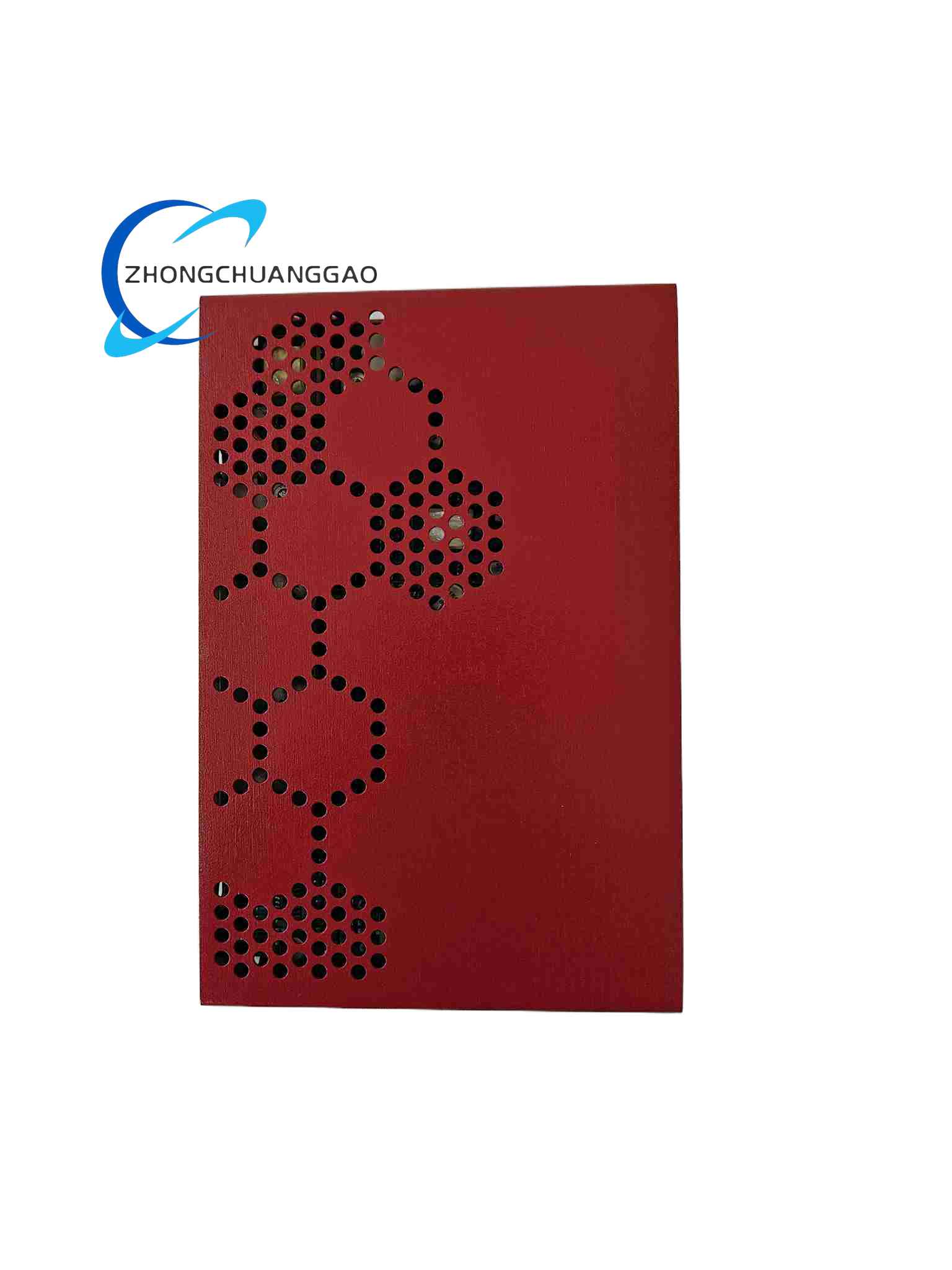
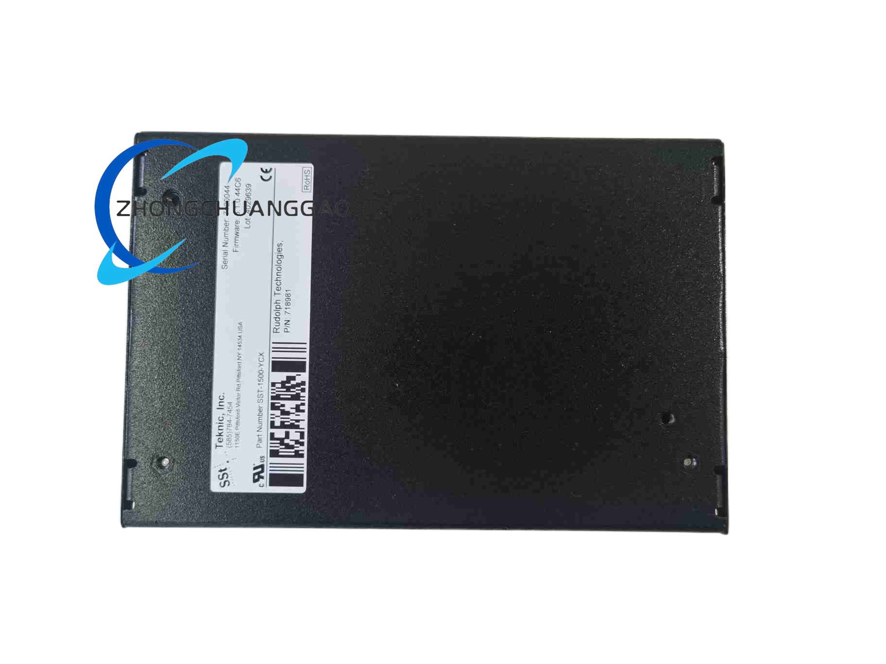
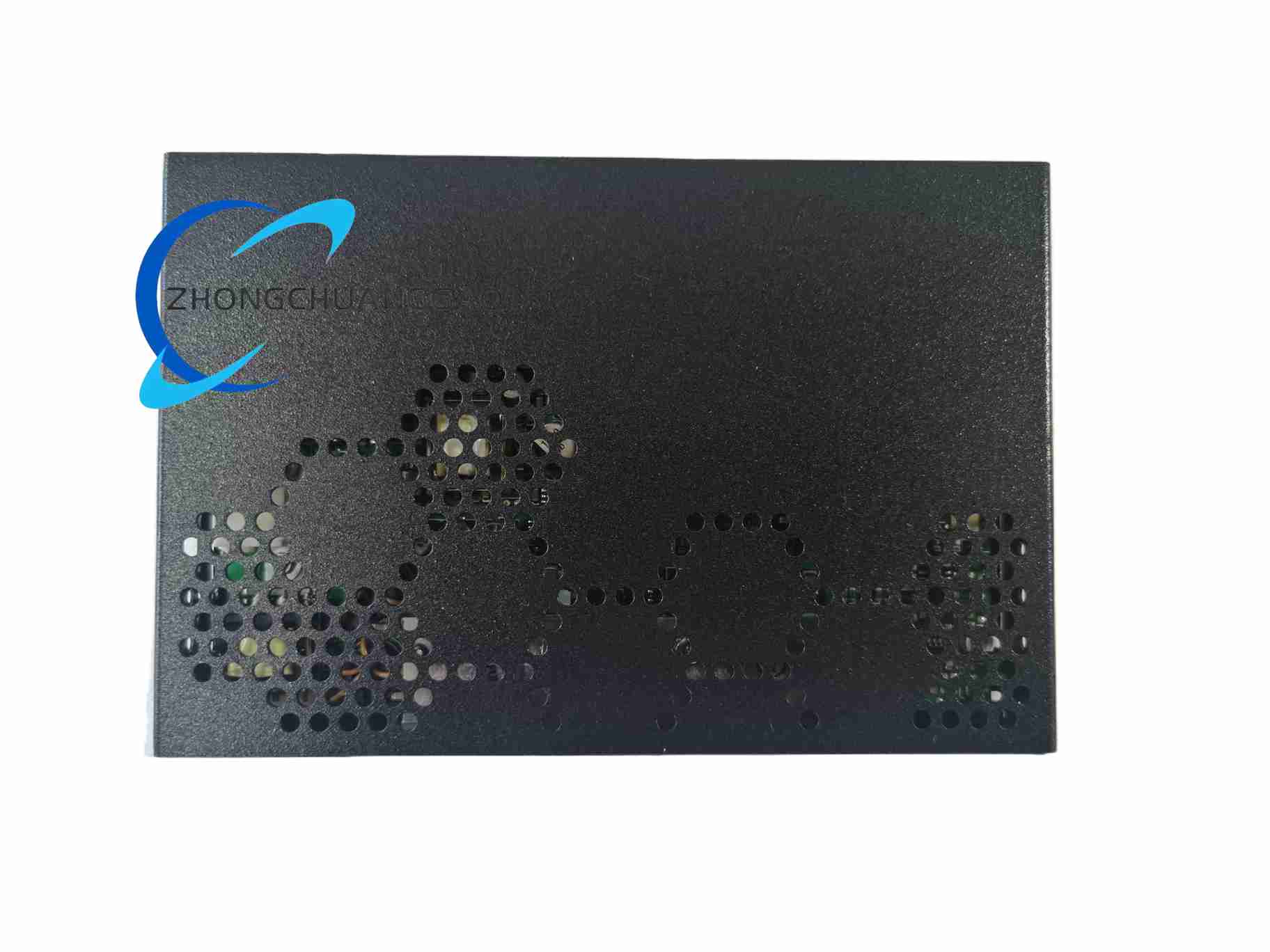
Description
Rated Power & Electrical Drive Parameters
- Matched servo motor rated output power: 1500W
- Supported motor type: Three-phase sinusoidal back EMF brushless permanent magnet AC servo motor with built-in electromagnetic holding brake
- Main circuit DC bus input voltage range: DC 48V ~ DC 320V wide-range direct current input
- Rated continuous three-phase motor drive RMS current: 12A
- Peak instantaneous output RMS current: 30A, sustainable for maximum 5 seconds
- Current control loop bandwidth: 4.5kHz high-speed current response
- Built-in dedicated brake drive circuit: Independent 24VDC high-current brake excitation output channel, maximum continuous brake output current 2A, directly driving the electromagnetic holding brake coil of the matched servo motor without external relay conversion; built-in brake delay release and delay lock logic, configurable brake action delay time via internal parameters to match mechanical axis motion timing and avoid brake friction wear during motor rotation.
- Main power switching device: Integrated silicon IGBT power transistor module with built-in temperature sensing thermistor and freewheeling flyback diodes
Motion Control Command Input Interface Specifications
- 2-channel differential line driver pulse train input, maximum input pulse frequency 4MHz, supporting CW/CCW dual-pulse, pulse+direction, A/B quadrature pulse three input modes
- 1-channel ±10V differential analog voltage input for speed and torque mode command signals
- Standard RS485 two-wire serial bus, native Modbus RTU communication protocol support
- Optional CANopen CiA 402 industrial real-time fieldbus expansion module for multi-axis synchronous coordinated motion control
- 8 optocoupler isolated configurable digital input points, 6 optocoupler isolated configurable digital output points; the digital output channel reserves dedicated parameter-assignable brake control signal output terminals for linkage with external auxiliary brake equipment if required.
Encoder Closed-Loop Feedback Interface Parameters
- Supported feedback devices: 2500-line incremental quadrature encoders, multi-turn absolute serial encoders supporting SSI and BiSS-C communication protocols
- Maximum supported absolute encoder resolution: 23-bit sub-micron positioning accuracy
- Signal transmission mode: LVDS low-voltage differential signal transmission, maximum stable transmission distance 50 meters between drive and motor
- Built-in real-time encoder signal fault detection logic, automatic torque cut-off and fault alarm upon signal loss, short circuit or signal distortion
Environmental Operating Specifications
- Continuous operating ambient temperature range: -10°C ~ +55°C
- Long-term storage temperature range: -45°C ~ +75°C
- Tolerable relative humidity: 5% ~ 90% non-condensing
- Mechanical vibration resistance standard: IEC 60068-2-6, 10–150Hz sinusoidal vibration, maximum acceleration 1.5g
- Mechanical shock resistance standard: IEC 60068-2-27, maximum instantaneous impact acceleration 15g
- Global compliance certifications: CE industrial machinery certification, UL industrial control safety certification, RoHS hazardous substance restriction standard, EMC Class B factory automation electromagnetic interference standard
Physical Dimension & Weight Data
- Overall outer dimensions (Height × Width × Depth): 165mm × 78mm × 132mm
- Net single unit weight: 1.28kg
- Mounting form factor: Vertical panel surface mounting, four corner through-hole fixing positions matching M4 stainless steel fixing bolts
Core Function Features
Multi-Mode Closed-Loop Motion Control Algorithms
Dedicated Built-In Motor Holding Brake Control Function (Core Differentiated Feature vs XCX)
- Independent integrated 24V brake power drive circuit: No external relay contactors required for motor brake coil driving; the internal dedicated power circuit directly supplies excitation current to the motor holding brake, simplifying cabinet wiring and reducing electrical component failure points caused by additional relays.
- Configurable brake timing delay logic via internal parameters: Two adjustable delay time parameters are provided: brake release delay time and brake lock delay time.
- Brake release delay: After the servo drive outputs a torque enable signal to start motor rotation, the drive maintains the brake locked state for the set delay time first, then outputs excitation current to release the brake, ensuring the motor generates stable output torque before mechanical braking is lifted, preventing gravity load axis sliding during brake release.
- Brake lock delay: When the servo drive receives a servo disable signal or triggers a fault torque cut-off, the drive continues to output motor torque to maintain axis position for the set delay time, then cuts off brake excitation current to lock the mechanical brake, eliminating workpiece falling or vertical axis free fall caused by delayed mechanical brake response after motor torque disappears.
- Brake fault real-time detection function: The built-in brake circuit continuously samples the coil current of the motor holding brake; if open-circuit (brake coil wire breakage) or short-circuit (brake coil insulation damage short circuit) faults are detected, the drive immediately triggers a dedicated brake fault alarm code, cuts off motor torque output synchronously and records the fault event in internal flash memory for later maintenance traceability.
Comprehensive Multi-Layer Hardware & Software Safety Protection System
Multi-Channel Industrial Communication & Digital I/O Control Functions
Equipment Parameter Configuration & Operating State Monitoring Functions
Material Composition & Structural Characteristics
Installation Requirements
Application Scenarios
- Vertical lifting automated equipment: Vertical material lifting linear axes of automated three-dimensional warehouses, vertical lifting cutting platforms of CNC machining equipment, vertical lifting feeding axes of packaging machinery
- Multi-joint industrial robot vertical joint axes: Vertical shoulder joint axes and vertical wrist joint axes of medium-load articulated assembly robots, vertical lifting joint axes of palletizing robots
- Precision vertical positioning medical and laboratory equipment: Vertical sample lifting test platforms of medical laboratory automatic detection equipment, vertical film feeding positioning axes of medical imaging auxiliary equipment
- Automated elevator-type material transfer machinery for electronic manufacturing: Vertical lifting transfer axes of PCB automatic production lines, vertical lifting loading axes of semiconductor wafer testing equipment
Working Principle
After the main control chip outputs a servo torque enable signal, the brake drive subsystem starts the preset brake release delay timer; after the timer counts down to zero, the internal brake power circuit outputs stable 24V excitation current to the motor brake coil, lifting the mechanical brake friction plate and allowing the motor to rotate freely. When a servo disable signal or fault torque cut-off signal is received, the brake drive subsystem activates the brake lock delay timer; the main power drive circuit continues to output holding torque to maintain axis position during the countdown process. Once the timer completes counting, the brake drive subsystem cuts off all excitation current output to the brake coil; the built-in brake spring of the motor pushes the friction plate to lock the motor rotor, realizing reliable mechanical holding braking for gravity load axes. The brake circuit current sampling module continuously monitors the coil excitation current during the entire brake operating cycle; abnormal current values corresponding to coil open-circuit or short-circuit faults trigger dedicated brake fault alarm logic synchronously.
Use Precautions
- Strictly prohibit parallel connection of multiple motor brake coils to the YCX model’s dedicated brake excitation output terminals. The internal brake drive circuit is designed with a maximum continuous output current limit of 2A, only supporting single servo motor holding brake coil driving; parallel connection of multiple brake coils will cause overcurrent burnout of the internal brake power circuit and trigger permanent hardware damage. If multiple brake axes need to be controlled simultaneously, configure independent SST-1500-YCX servo drives for each axis separately.
- Do not arbitrarily modify the brake release delay and brake lock delay timing parameters to extremely short values during equipment parameter debugging. Excessively short brake release delay time will lead to insufficient motor torque output before the mechanical brake is released, causing gravity load axis sliding and workpiece falling; excessively short brake lock delay time will result in the mechanical brake locking the rotor before the motor output holding torque disappears, generating severe mechanical friction wear on the brake friction plate and greatly shortening the service life of the motor holding brake assembly. Adjust the two delay parameters step by step according to the actual mechanical movement speed and load weight of the equipment axis, and conduct multiple repeated motion tests to confirm stable braking timing without sliding or friction wear phenomena before formal mass production operation of the equipment.
Reviews
There are no reviews yet.