Description
Technical Specifications
Functional Features
- Dual independent SLC loops allow segmentation of large buildings into two monitored zones
- Full addressability — each device has a unique address for precise location identification
- Auto-learning device programming — devices are automatically detected and assigned addresses upon connection
- On-board LCD display shows real-time system status, alarm conditions, and trouble signals
- LED indicator panel provides at-a-glance visual status of power, alarm, trouble, and supervisory conditions
- Event logging — records up to 1,000 time-stamped events in non-volatile memory
- Programmable Form C relay outputs — configurable for fire alarm, supervisory, trouble, or custom functions
- 2 supervised NAC circuits — Class A or Class B style notification appliance circuit supervision
- RS-232 serial communication — supports connection to remote annunciators, printers, and building management systems (BMS)
- Panel-mounted initiation — built-in dry-contact initiator inputs for manual pull stations or external triggers
- Silence and Reset controls — local panel-mounted push buttons for system acknowledgment
- Latching vs. non-latching alarm modes — user-selectable alarm confirmation behavior
Performance Parameters
Material Composition
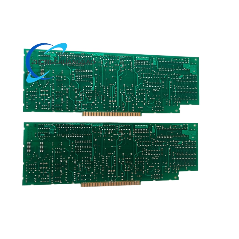
Structural Features
- Wall-mount or cabinet-mount configuration — includes pre-drilled mounting holes and removable backplate
- Hinged front bezel — allows access to terminal blocks and internal components without full panel removal
- Modular terminal block layout — organized by loop (Loop 1 and Loop 2), power, NAC, and relay sections
- DIN rail compatible — internal components mounted on standard DIN rail for serviceability
- Battery compartment — accessible from the front of the panel, battery is user-replaceable without tools
- Lockable front cover — tamper-resistant design to prevent unauthorized access or configuration changes
- Cable entry points — top and bottom cable knockout holes (multiple sizes) for clean wiring entry
- Grounding stud — dedicated chassis ground point, green-yellow wire connection
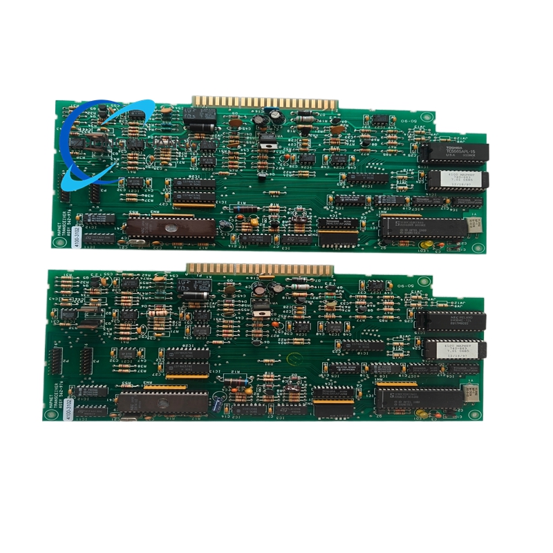
Working Principle
The Simplex 4100-3102 operates as a microprocessor-based addressable fire alarm control panel. The central processing unit (CPU) continuously polls each addressable device on both SLC loops via a digital communication protocol. Each device transmits its status (normal, alarm, trouble, supervisory) and unique address back to the panel. The CPU evaluates incoming signals against programmed alarm thresholds. Upon confirmation of a valid alarm condition, the panel activates the appropriate NAC circuits to energize notification appliances (horns, strobes, bells). Simultaneously, the panel triggers programmable relay outputs for building automation interface, elevator recall, HVAC shutdown, or other life safety functions. All events are time-stamped and stored in non-volatile memory for later retrieval. The 24 VDC standby battery automatically takes over during primary power failure, ensuring continuous monitoring and alarm capability for a minimum of 4 hours under full alarm load.
Advantages and Highlights
- Dual-loop architecture — provides redundancy and zoning flexibility for large facilities
- Full addressability on both loops — up to 316 devices with individual device identification
- Auto-address learning — eliminates manual address programming, reducing installation time
- Non-volatile event memory — retains up to 1,000 events even during total power loss
- RS-232 communication — seamless integration with remote annunciators, printers, and BMS platforms
- 4 programmable relays — versatile interface for third-party building systems
- 2 supervised NAC circuits — Class A or Class B operation for code-compliant notification
- UL 864 9th Edition listed — meets the latest fire alarm control panel standard
- Compact form factor — fits standard fire alarm cabinet or wall-mount applications
- Low standby current draw — minimizes battery drain, extends battery life
- Field-replaceable battery — no special tools required for battery replacement
Applicable Industries
Model Series Comparison (4100ES Family)
Note: The last digit of the model number indicates loop configuration. The third digit indicates NAC circuit count. The 4100-3102 specifically denotes a dual-loop panel with 2 NAC circuits.
Installation Requirements
- Mounting Surface: Flat, rigid, non-combustible wall or inside a listed fire alarm cabinet
- Mounting Height: Panel center should be installed at 5.0 feet (1.5 m) above finished floor per NFPA 72 recommendations
- Clearance: Minimum 36 inches (914 mm) of clear working space in front of the panel
- Cabinet Size (if used): Minimum 24 in × 18 in × 6 in (610 mm × 457 mm × 152 mm) cabinet recommended
- Wiring: Use UL listed, fire-rated cable (CMP or CMR rated) for all SLC loop wiring
- Wire Gauge: 18 AWG to 22 AWG stranded or solid copper for SLC loops; 14 AWG minimum for NAC circuits
- Loop Wiring Topology: Class A (Style A or Style B) or Class B — per NFPA 72 and local AHJ requirements
- Grounding: Panel chassis must be connected to building equipment grounding conductor using green or green-yellow wire, minimum 12 AWG
- Primary Power: Dedicated 120 VAC, 60 Hz, 15 A or 20 A circuit with overcurrent protection
- Battery Connection: Connect 24 VDC sealed lead-acid battery to dedicated battery terminals before applying primary power
- Communication Wiring: RS-232 cable maximum length is 50 feet (15 m) without repeater
- Environmental Conditions: Install in areas within 32°F to 104°F (0°C to 40°C) temperature range
- Seismic Bracing: Required in seismic zones per local building code (IBC Chapter 16)
Usage Precautions and Notes
- Never disconnect the standby battery while primary power is applied — this can cause panel reset and loss of event memory
- Replace the 24 VDC battery every 4 to 5 years regardless of apparent condition — sealed lead-acid batteries degrade over time
- Do not exceed 158 devices per SLC loop — exceeding this limit will cause communication errors and unreliable operation
- Do not exceed 4,000 feet (1,219 m) of total SLC loop wiring per loop — longer runs require loop extenders or repeaters
- Perform a full system test at least once per year per NFPA 72 requirements
- Do not cover or obstruct the LCD display or LED indicators — visual status monitoring is required for code compliance
- All wiring must be performed by a licensed fire alarm technician per NFPA 72 and local jurisdiction requirements
- Do not modify panel firmware or programming without authorized Honeywell/SimplexGrinnell service personnel
- Lock the front panel cover after programming is complete to prevent unauthorized tampering
- Record all programming changes and device additions in the system log book for audit purposes
- In the event of a trouble condition, investigate and resolve within 24 hours per NFPA 72 supervision requirements
- Do not use the panel for any purpose other than fire alarm signaling — it is not a general-purpose control panel
- Verify all device addresses after any battery replacement or panel reset — auto-learn will re-detect devices but addresses must be confirmed
Reviews
There are no reviews yet.