
Product Short Description
Product Brief
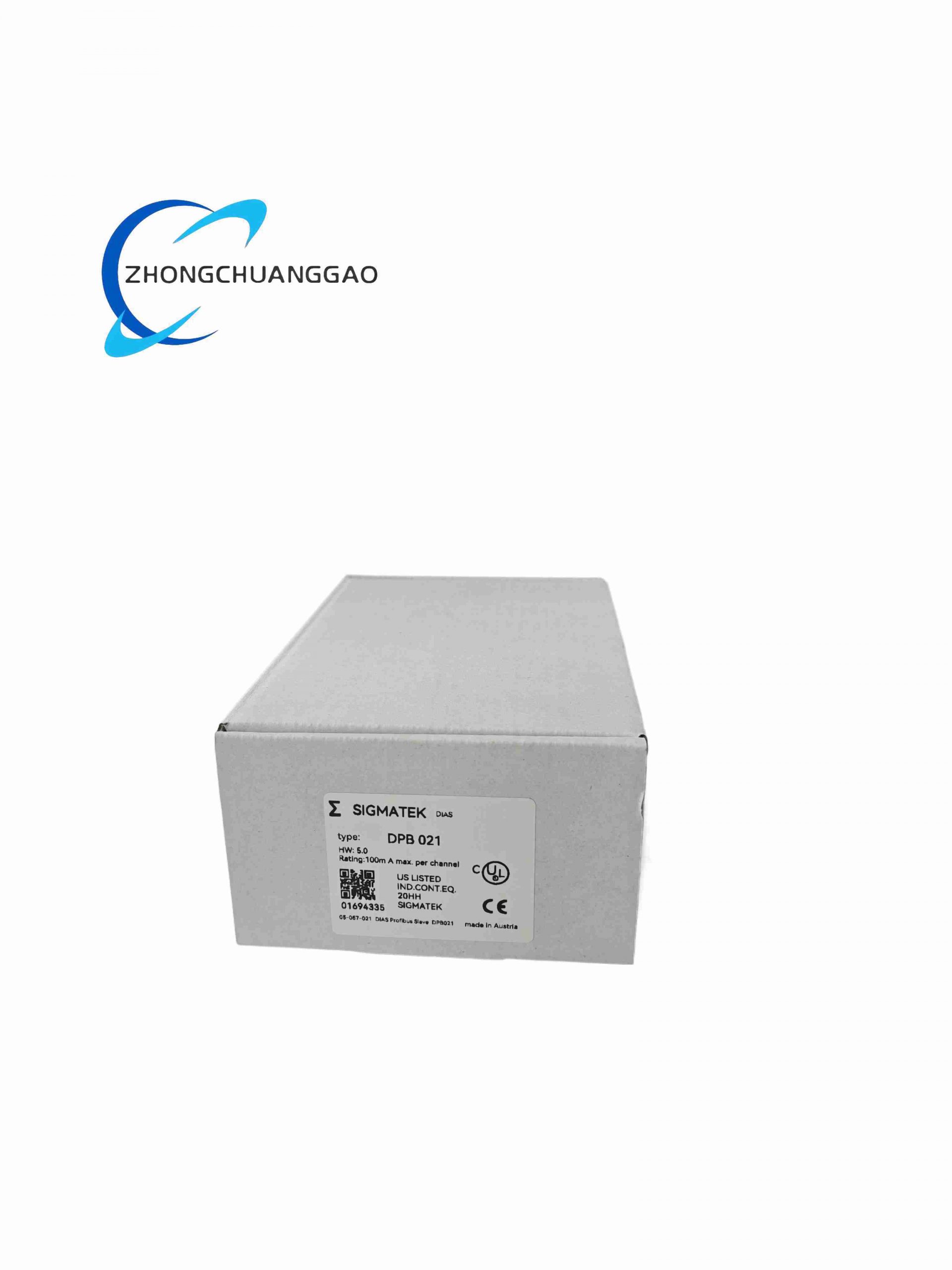
Dual-purpose digital mixed I/O expansion slave module of SIGMATEK DIAS rack automation system, fixed channel configuration of 16 isolated digital input and 8 relay digital output channels, designed for collecting field limit switches, proximity sensors and outputting control signals to valves, contactors and indicator lights, communicates with DNC series CPU master controllers via DIAS internal backplane bus.
Description
Technical Specifications
- Model Series: SIGMATEK DIAS DPB Digital Mixed I/O Expansion Module Series
- Digital Input Channels: 16 isolated universal NPN/PNP DI channels
- Digital Output Channels: 8 SPDT relay DO channels
- DI Signal Rated Voltage: 24 VDC field sensor signal
- DO Relay Single Channel Max Load: 5 A / 250 VAC resistive load
- Channel Isolation Voltage: 1500 VAC between field circuit and DIAS backplane bus
- Backplane Bus: SIGMATEK proprietary DIAS high-speed internal bus
- DI Signal Response Delay: ≤ 0.3 ms
- Relay Mechanical Service Life: 10 million switching cycles under rated load
- Rated Module Supply Voltage: 24 VDC ±10% rack backplane power
- Power Consumption: 11 W full-load all relay output activation
- Operating Temperature Range: -20 °C ~ +60 °C
- Storage Temperature Range: -40 °C ~ +85 °C
- Relative Humidity Tolerance: 5%–95% non-condensing
- Mounting Standard: SIGMATEK DIAS standard DIN rail rack slot
- Protection Class: IP20 module body
- Dimension: 125 mm (H) × 45 mm (W) × 70 mm (D)
- Net Weight: 405 g
Functional Features
- 16-way universal NPN/PNP digital input compatible with all mainstream 24 VDC industrial proximity and limit sensors
- 8-way high-capacity SPDT relay output with built-in arc suppression circuit to extend relay service life
- Independent LED status indicator for each DI/DO channel on front panel for real-time signal status visualization
- Per-channel hardware short-circuit protection for relay output terminals to avoid single-channel fault causing full module shutdown
- Full hot-swap compatible with all DIAS rack slots without master CPU power-off
- Built-in hardware signal filtering circuit to eliminate field sensor transient pulse interference
- Automatic channel fault signal upload to DNC master controller via DIAS backplane bus for system fault diagnosis
Performance Parameters
- DI Channel Recognition Threshold: 10 VDC low level / 18 VDC high level
- Surge Withstand Capacity: 2 kV ESD contact discharge on all field I/O terminals
- Vibration Resistance: 10 Hz – 1500 Hz, 5 g continuous cabinet vibration
- DI Signal Filtering Time: Configurable 0.1 ms – 10 ms hardware filter
- Max Field Wiring Distance: 100 m shielded twisted pair for DI/DO signal cables
Material Composition
- Outer Housing: Black extruded aluminum alloy hard anodized anti-corrosion frame
- Main PCB: FR4 multi-layer industrial fiberglass circuit board with isolation barrier routing
- Input Isolation Components: High-speed wide-temperature optocouplers for each DI channel
- Output Relay: Silver alloy contact SPDT industrial signal relays with arc suppression diodes
- Terminal Blocks: Gold-plated phosphor bronze anti-loosening screw terminal blocks
- Backplane Connector: Gold-plated edge finger connector for DIAS rack bus docking
Structural Characteristics
- Narrow single-slot 45 mm width DIN rail plug-in rack module layout for compact cabinet stacking
- Front panel split indicator zones: 16 DI channel LED group and 8 DO channel LED group for fast status identification
- Rear gold finger connector for direct electrical connection with DIAS rack backplane bus
- Two independent wiring terminal blocks on module bottom: separate DI input terminal zone and DO output terminal zone to avoid wiring confusion
- Internal physical isolation barrier separates digital input optocoupler circuit and relay output power circuit to eliminate cross-channel interference
- Dual side elastic locking latches for vibration-resistant fixed installation inside DIAS rack slots
Working Principle
24 VDC digital signals from field proximity sensors, limit switches and safety interlock devices transmit to 16 optocoupler isolated digital input channels. Hardware signal filtering circuits eliminate transient interference pulses; optocouplers convert field electrical signals to internal logic levels and transmit digital state data to DNC master CPU via DIAS backplane bus. Control logic commands issued by the master CPU are received by DPB021 internal processing circuit, driving 8 SPDT relay coils to switch external AC/DC load equipment such as solenoid valves and auxiliary contactors. Built-in arc suppression circuits absorb reverse electromotive force generated during relay contact breaking to protect relay contacts from ablation. Hardware short-circuit monitoring circuits detect overload current on each relay output channel and cut off single-channel output instantly without affecting other DI/DO channels. Each channel real-time signal status and fault state is uploaded to the master controller for centralized equipment monitoring and alarm logic execution.
Advantage Highlights
- Integrated 16DI + 8DO mixed I/O design reduces the total number of rack expansion modules required for field signal collection
- Universal NPN/PNP digital input eliminates manual jumper adjustment for different sensor wiring types
- High-capacity relay output directly drives industrial solenoid valves and small contactors without intermediate relay conversion
- Per-channel independent short-circuit protection prevents full module failure caused by single field wiring short fault
- Front panel channel-by-channel LED indicators allow rapid on-site fault location without software debugging
- Full mechanical and electrical compatibility with SIGMATEK DNC series master CPU and all DIAS rack hardware
Applicable Industries
Automated packaging machinery interlock signal collection, injection molding machine safety limit monitoring, woodworking CNC equipment valve control, hydraulic lifting platform sensor signal acquisition, metal processing stamping equipment safety interlock control, textile production line actuator drive
Installation Requirements
- Install DPB021 into vacant slot of SIGMATEK DIAS DIN rail rack; fasten dual side locking latches to prevent module sliding under cabinet vibration
- Reserve minimum 10 mm vertical ventilation gap between DPB021 and adjacent rack modules for heat dissipation
- Field DI/DO signal cables adopt shielded twisted pair wiring, single-point shielding grounded at cabinet PE terminal only
- Cabinet main PE grounding resistance ≤ 4 Ω to fully activate EMC anti-interference performance of isolation circuits
- Stabilize rack backplane 24 VDC power supply before hot-swap replacement of the module
- Separate field signal wiring from high-power motor and inverter power cables with minimum 20 cm clearance inside cabinet
Operation & Maintenance Precautions
- ESD anti-static wrist strap mandatory during module disassembly and field wiring modification
- Conduct quarterly inspection of relay output terminal screw tightness to avoid loose contact heating
- Replace internal relay assemblies when accumulated switching cycles exceed 8 million times to prevent contact ablation failure
- Do not install DPB021 adjacent to high-frequency variable frequency drive modules to avoid signal false triggering interference
- Store spare DPB021 modules in sealed anti-static packaging with silica gel desiccant packs for humidity control
- Cut off all field sensor and actuator external power supply before disassembling DI/DO wiring terminal blocks
-500x500.jpg)
Reviews
There are no reviews yet.