
Product Short Description
Product Brief Introduction
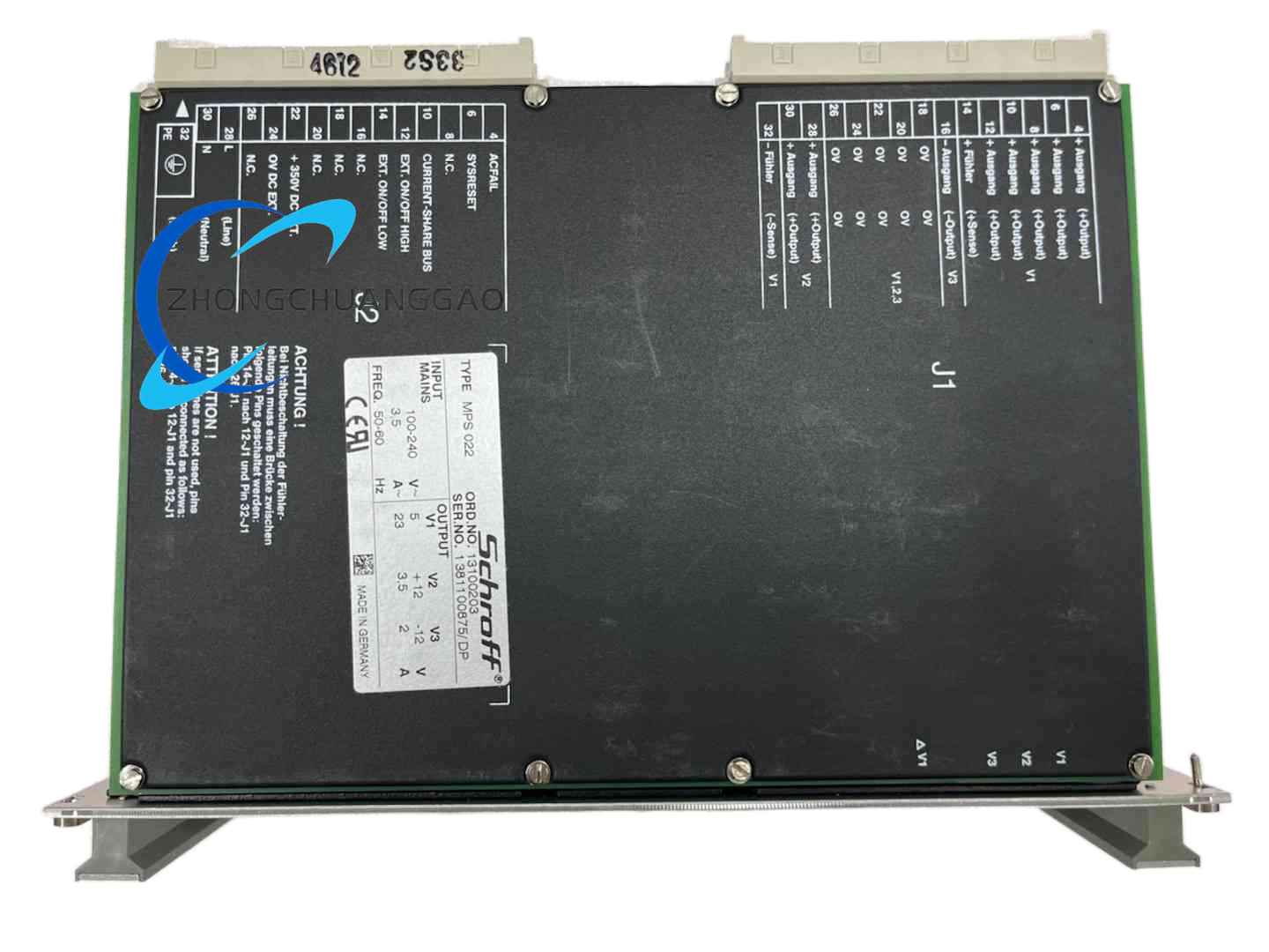
High-efficiency plug-in power unit exclusively designed for standard VMEbus embedded subrack systems, delivering stable multi-channel DC output for industrial computing, military control, and test measurement racks. Built for 24/7 continuous heavy-duty industrial operation with redundant parallel power expansion capability.
Description
Core Technical Specifications
- Input Range: Universal AC 90–264 VAC (50/60 Hz); DC backup 130–350 VDC
- Rated Total Output Power: 224 W
- Output Channels:
- Primary: +5 VDC / 28 A
- Auxiliary 1: +12 VDC
- Auxiliary 2: -12 VDC
- Conversion Efficiency: ≥80% full load
- Output Ripple Noise: <10 mVpp on +5V main rail
- Form Factor: 6U height, 3HP width, 19-inch Eurocard plug-in
- Operating Temperature: 0 °C ~ +50 °C (natural convection cooling)
- Protection Circuits: Overvoltage (OVP), Overcurrent (OCP), Short-Circuit Foldback, Over Temperature Thermal Shutdown
- Communication & Parallel Function: Passive current-sharing bus for N+1 redundant parallel operation; Power OK / Fault LED status indicators
- EMC Compliance: EN 61000-6-2 industrial immunity standard
Function & Performance Features
- Integrated Active Power Factor Correction (PFC) to minimize grid harmonic distortion, improve power utilization efficiency
- Hot-swap pluggable design, allows module replacement without full system power cut
- Low electromagnetic interference, no signal distortion to adjacent VME backplane boards
- Automatic load balancing when multiple modules work in parallel, equal power distribution to extend service life
- Built-in fault latch function: power failure state remains locked until manual power reset for easy fault diagnosis
- Wide input voltage tolerance, adapts to unstable factory power grids and mobile industrial equipment power supplies
Working Principle
- AC input passes EMI filter and active PFC circuit to rectify stable high-voltage DC bus
- High-frequency forward switching topology converts high-voltage DC to isolated multi-channel low-voltage DC
- Independent closed-loop voltage feedback for each output rail to maintain constant voltage under dynamic load fluctuation
- Current-sharing bus signal synchronizes switching phase of parallel modules to eliminate output current imbalance
- Real-time temperature, voltage and current monitoring chips trigger protective shutdown when parameters exceed threshold
Material Composition & Structural Characteristics
- Outer Chassis: Cold-rolled steel sheet with matte black anti-corrosion powder coating, shock-resistant
- Heat Dissipation Component: Large-area extruded aluminum fin radiator integrated on rear side for passive heat dissipation
- Internal PCB: High-temperature FR4 flame-retardant circuit board with tin-plated copper traces
- Connector Interface: Industrial-grade H15 VME standard gold-plated backplane connector, anti-oxidation and vibration-resistant
- Mechanical Frame: Standard Eurocard aluminum guide rail frame, matched with SCHROFF 6U series subracks
Installation Requirements
- Must be installed inside standard 19-inch 6U SCHROFF VME subrack, fixed via front panel locking screws
- Maintain minimum 20 mm vertical clearance above and below module for natural air convection; no external fan blocking radiator fins
- Backplane wiring must strictly separate power cable and signal cable to avoid cross-interference
- Parallel redundant installation requires unified current-sharing bus wiring between all power modules
- Ground wire must connect module ground terminal to rack protective earth for surge protection
Application Scenarios
- Military embedded VME control cabinets
- Industrial automated test equipment (ATE)
- Railway vehicle on-board control systems
- Medical imaging equipment rack power supply
- Aerospace ground test simulation platforms
- Factory process monitoring VME industrial computers
Usage Precautions
- Do not operate beyond 50 °C ambient temperature; high temperature will drastically shorten electrolytic capacitor lifespan
- Strictly prohibit reverse connection of AC/DC input terminals, will cause permanent internal circuit burnout
- When replacing hot-swap modules, wait 30 seconds after pulling out for internal residual charge discharge
- Regularly clean aluminum radiator dust every 3–6 months in dusty workshop environments
- Avoid installation near strong electromagnetic equipment such as high-power inverters and welding machines
- N+1 redundant parallel groups cannot exceed 8 units simultaneously to prevent current-sharing bus overload
Reviews
There are no reviews yet.