
Product Short Description
Product Brief Introduction
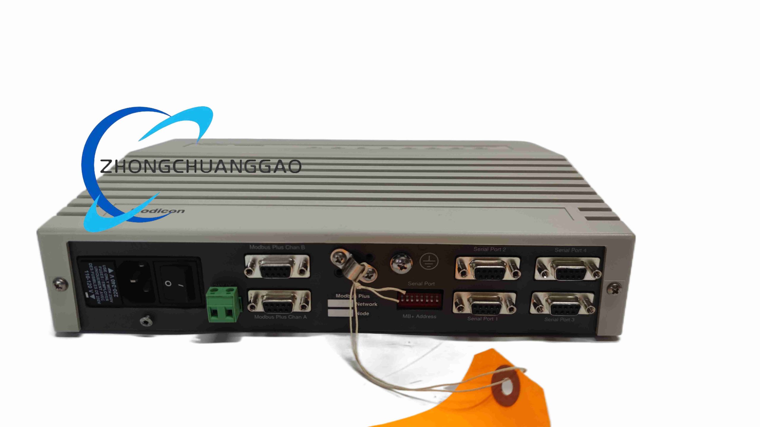
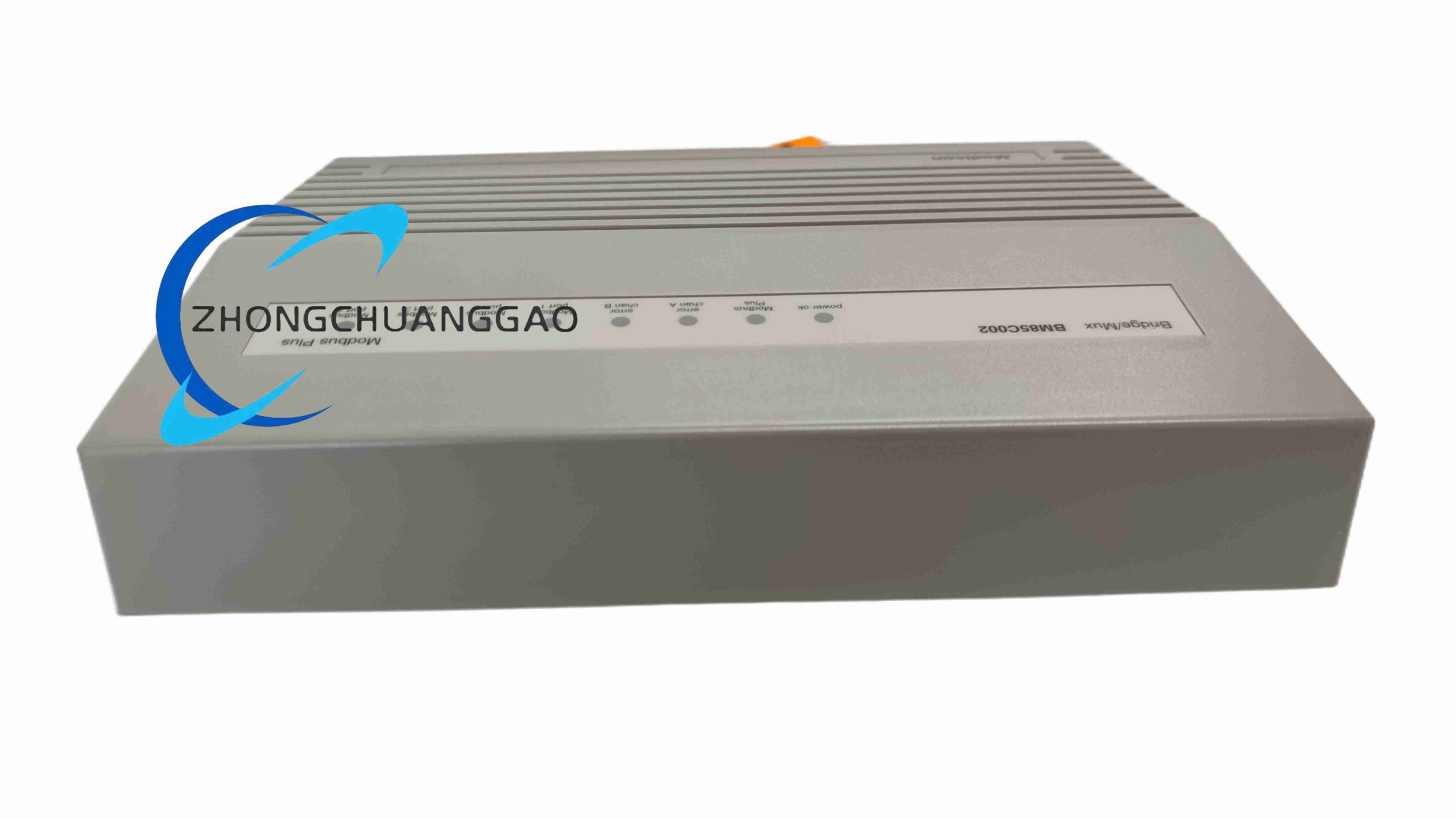
NW-BM85C002 is a dedicated industrial communication bridge multiplexer module developed by Schneider Electric for Modicon Quantum series programmable logic controllers. The core function is to realize signal multiplexing, network segment bridging and node expansion of Modbus Plus industrial fieldbus networks. It carries dual independent Modbus Plus communication ports, supports up to 64 bus nodes per communication segment, solves the limitation of insufficient node capacity of single Modbus Plus bus cable
Description
Core Technical Performance Parameters
- Supported Fieldbus Protocol: Modbus Plus (MB+) Industrial Token Passing Bus
- Maximum Communication Baud Rate: 1 Mbps
- Number of Independent MB+ Communication Ports: 2 Isolated Dual Ports
- Single Segment Maximum Supported Bus Nodes: 64 Devices
- Operating Power Supply Voltage: 24 VDC (115~220 VAC wide voltage optional power version)
- Module Power Consumption: Max 2 W under full-load communication operation
- Operating Ambient Temperature: -20°C ~ +60°C
- Storage Temperature: -40°C ~ +70°C
- Relative Humidity: 5% ~ 95% Non-Condensing
- Physical Dimensions (L×W×H): 70 mm × 70 mm × 30 mm
- Net Module Weight: 100 g
- Backplane Compatibility: Modicon Quantum PLC 14-slot / 16-slot / 26-slot CPU backplane
- Electromagnetic Compatibility Standard: CE, UL, IEC 61000-6-2 industrial EMC certification
Functional Feature Highlights
- Dual isolated Modbus Plus bus port design, realizes bidirectional transparent data bridging between two independent MB+ network segments, automatically forwards token passing signals and real-time process data
- Built-in hardware signal amplification and signal reshaping circuit, eliminates bus signal attenuation caused by long-distance cable transmission, maximum single bus cable extension distance up to 450 meters
- Multiplexer function integrates multiple scattered field Modbus Plus slave devices into a unified main control network segment, greatly reduces the number of communication expansion modules required for large-scale distributed automation systems
- Full hot-swap support; module plugging, removal and replacement can be completed while the PLC mainframe is powered on and running, no production line shutdown required for maintenance
- On-board LED status indicator lights for each communication port, separate power supply indicator, bus fault alarm indicator; real-time visual display of module power status, bus communication link status, token passing error, short circuit fault
- Built-in hardware bus short-circuit protection circuit; short circuit fault on one MB+ port will not affect the normal communication operation of the other independent bus port, fault isolation function prevents full network paralysis
- Compatible with all Modicon Quantum CPU models, Modbus Plus remote I/O modules, variable frequency drives, human-machine touch screens, temperature controllers and other MB+ bus industrial automation slave equipment
- Compact ultra-small modular structure, occupies only one single slot position on the Quantum PLC backplane, maximizes cabinet internal space utilization rate
Material Composition & Structural Characteristics
- Module Outer Housing: High-strength black ABS engineering plastic shell, UL94-V0 flame retardant grade, anti-static surface coating treatment
- Internal Core Circuit Board: FR4 fire-resistant fiberglass PCB, multi-layer shielding copper foil circuit design to suppress electromagnetic interference
- Communication Interface Connector: Gold-plated Modbus Plus dedicated 9-pin D-SUB female connector, 15μm thick gold plating to prevent long-term plug wear and oxidation contact failure
- Backplane Contact Pin Row: Phosphor bronze elastic contact pins with full gold plating, excellent electrical conductivity and anti-fatigue plug durability
- Internal Core Chip: Industrial-grade high-speed fieldbus protocol processing microcontroller, isolated optocoupler signal isolation components for dual communication ports
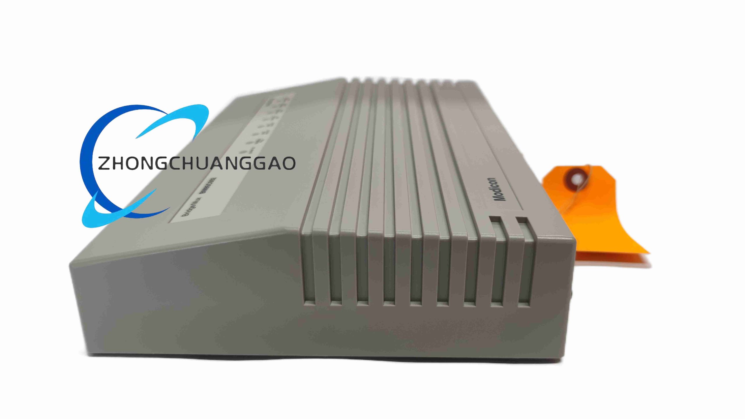
- Heat Dissipation Structure: Hollow grid plastic shell design, natural convection air flow channel for internal circuit heat dissipation, no built-in cooling fan for maintenance-free operation
- Mounting Locking Mechanism: Spring plastic locking buckle on both sides of the module, firmly locks the module to the PLC backplane slot to avoid loose contact caused by cabinet long-term vibration
Working Principle
The NW-BM85C002 module is inserted into the Modicon Quantum PLC backplane slot, powered by the PLC backplane 24VDC power supply, and establishes internal high-speed parallel data communication with the PLC CPU through the backplane bus. The module integrates two independent Modbus Plus token-passing bus physical layer transceivers with complete electrical isolation between the two channels. When Modbus Plus bus data frames and token signals enter one of the module’s MB+ ports, the internal protocol microcontroller receives, reshapes, amplifies and buffers the signal data, then transparently forwards the complete token passing sequence and process data frames to the second independent MB+ communication port without modifying data content or communication timing. For multiplexer expansion applications, multiple slave devices connected to the secondary MB+ bus segment are logically mapped into the primary main control bus segment, allowing the PLC CPU to read and write data to all remote slave nodes uniformly through the bridge module, completely transparent to the upper-level control program. Each communication port carries independent hardware short-circuit detection logic; when bus cable short circuit occurs, the port automatically cuts off the bus power supply and triggers the fault LED alarm, while the other communication channel continues normal bridging operation to realize fault isolation.
Installation Mandatory Requirements
- Backplane Slot Installation: Insert the module into any unused single slot position of Modicon Quantum PLC backplane; avoid installing the module adjacent to high-power analog output modules and servo drive power supply modules to reduce electromagnetic interference
- Locking Operation: After fully inserting the module into the backplane slot, press the plastic locking buckles on both sides until a clear “click” sound is heard to confirm complete locking and prevent loose contact under vibration
- Communication Cable Wiring: Use dedicated shielded Modbus Plus twisted-pair communication cable for all bus wiring; cable shielding layer single-point grounding at the PLC cabinet ground copper bar, two-point grounding is strictly prohibited to avoid ground loop interference
- Bus Topology Specification: Each MB+ port must adopt standard daisy-chain bus topology; star topology wiring without signal repeater bridge is forbidden, which will cause severe bus signal reflection and communication failure
- Grounding Requirement: Connect the metal shielding shell of each D-SUB communication connector to the cabinet protective ground copper bar with a short 2.5mm² copper grounding wire
- Operating Environment Space: Maintain a minimum 15mm vertical air convection gap above and below the module housing inside the PLC cabinet, no other modules or wiring harnesses block the module heat dissipation grid holes
Typical Industrial Application Scenarios
- Large-scale discrete manufacturing automobile assembly line Modicon Quantum PLC distributed control systems
- Petrochemical plant process control central PLC cabinets with multiple remote field Modbus Plus I/O stations
- Water treatment plant multi-station centralized automation control systems with long-distance field bus wiring
- Metallurgy steel rolling production line multi-drive coordinated control Modbus Plus bus network expansion
- Building intelligent centralized energy monitoring large-scale Modicon Plus slave equipment centralized access
- Food & beverage packaging multi-station distributed PLC control network segment isolation and bridging
Operation & Maintenance Precautions
- When performing hot-swap replacement maintenance, hold the plastic module housing only; direct pulling of the communication cable connected to the D-SUB port is forbidden, which will damage the internal circuit soldering pins
- Inspect the module communication port LED indicator status every 7 days for continuous 24/7 factory operation; flashing fault LED indicates bus short circuit, broken cable or node address conflict fault, which must be eliminated immediately to avoid data communication loss
- Every 6 months, power off the PLC cabinet and remove the module, use dry compressed air (0.25MPa pressure max) to blow dust out of the module heat dissipation grid holes; wipe the D-SUB connector gold-plated pins with isopropyl alcohol cotton swabs to remove oxidation dust
- Do not modify the internal PCB circuit or replace communication port optocoupler and protocol chip with non-original Schneider spare parts; incompatible alternative components will cause Modbus Plus token passing timing disorder and full bus communication breakdown
- During cabinet lightning surge maintenance, confirm the cabinet protective grounding copper bar has reliable low-resistance connection to factory building ground grid; poor grounding will cause surge voltage to damage the module internal communication chip
- Store spare modules in sealed anti-static packaging bags when not in use; direct contact of module circuit pins with metal conductive objects will cause static electricity breakdown of delicate internal protocol processing chips
Reviews
There are no reviews yet.