
Product Short Description
Product Overview
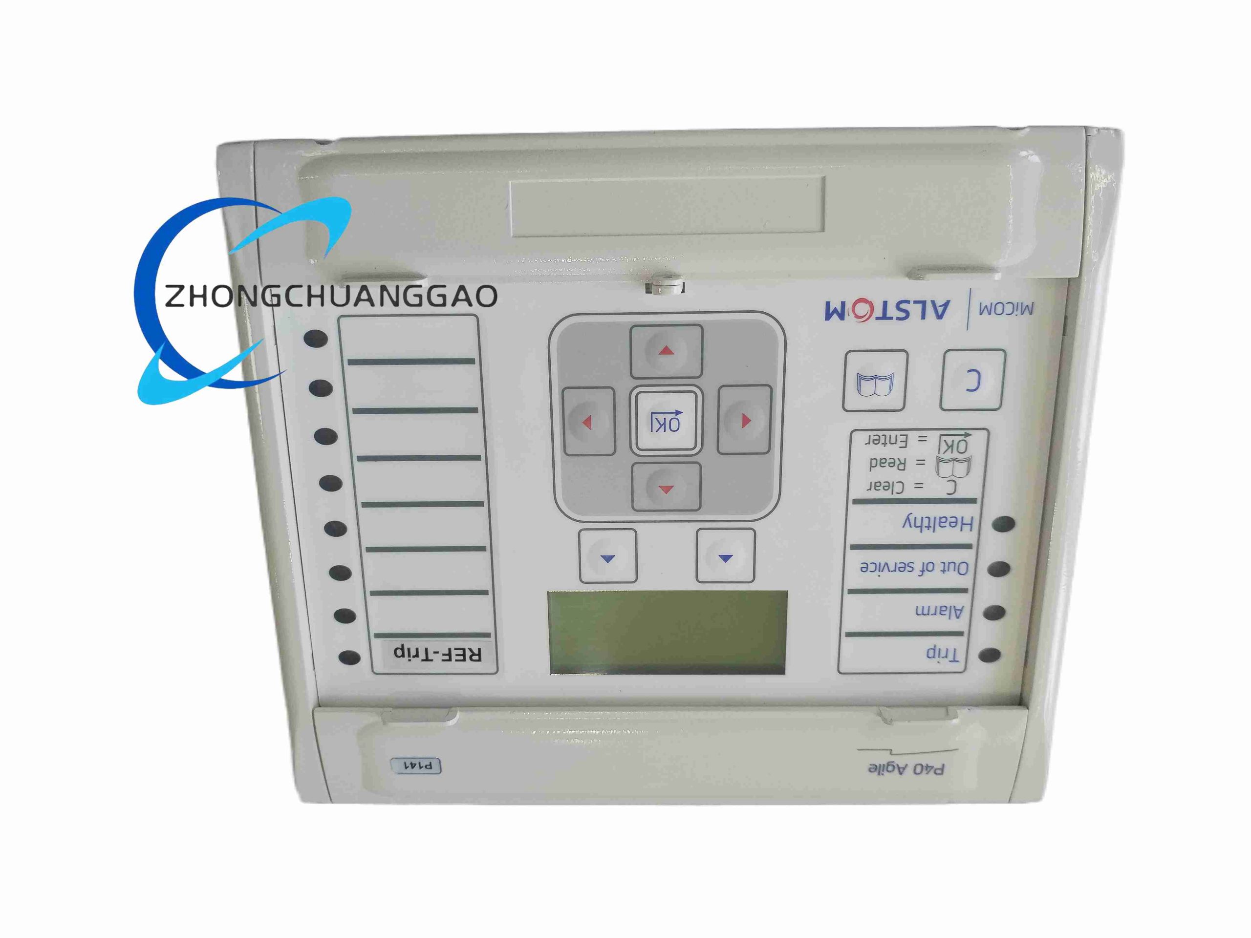
MiCOM P40 AGILE is a compact, fully numerical grid protection relay developed by Schneider Electric for medium-voltage distribution feeders. It integrates measurement, protection, control, fault recording, communication and human-machine interaction in a single unit, designed for cost-sensitive industrial, commercial and utility distribution networks. The AGILE variant optimizes firmware logic for fast fault tripping and simplified configuration workflows.
Description
Core Technical Specifications
- Power Supply: 24–250 VDC / 85–265 VAC universal auxiliary supply
- Rated Measurement Inputs: 1A / 5A CT secondary current; 100V VT secondary voltage
- Operating Temperature Range: -40°C to +70°C storage; -20°C to +60°C continuous operation
- Protection Trip Time: Minimum 8ms instantaneous overcurrent trip
- Communication Interfaces: Modbus RTU, IEC 60870-5-103, DNP3, Ethernet TCP/IP optional expansion
- Fault Recording Capacity: 1000 fault event logs; 50 cycle high-resolution oscillography storage
- Digital I/O Channels: 12 binary input channels, 8 relay output contacts (5A breaking capacity)
Functional Features
- Comprehensive protection algorithms: Phase overcurrent, earth fault, negative sequence overcurrent, thermal overload, under/over voltage, loss of voltage, reverse power protection
- Adaptive AGILE logic: Automatically adjusts protection curve parameters based on real-time feeder load data to avoid nuisance tripping during motor startup or load surge
- Built-in metering: 3-phase active/reactive power, power factor, energy accumulation, harmonic distortion measurement up to 31st harmonic
- Local HMI: Backlit LCD display, physical navigation pushbuttons, LED status indicators for trip, alarm, power, communication
- Firmware upgradable via USB or Ethernet without hardware disassembly
- SIL 2 functional safety certification for critical distribution feeder applications
Application Scenarios
- Medium voltage (3.3kV ~ 33kV) industrial factory distribution feeders
- Commercial building substation main & backup feeders
- Rural utility grid overhead line and underground cable protection
- Small-scale renewable energy grid interconnection (solar/wind farm low-voltage feeder)
- Pump, fan, compressor motor feeder protection in chemical, mining and water treatment plants
Material Composition & Structural Characteristics
- Housing Material: Flame-retardant ABS+PC alloy enclosure, UL94 V-0 fire resistance rating
- Internal PCB: Double-sided industrial FR4 printed circuit board with tin-lead free gold-plated contact terminals
- Front Panel: Anti-scratch tempered glass protective layer for LCD screen; silicone rubber sealed pushbuttons for dust and moisture resistance
- Mechanical Structure: Standard 4U 19-inch rack-mount chassis; compact depth design (140mm cabinet depth compatible); fully sealed internal module compartment to prevent dust ingress
Working Principle
The relay samples real-time current and voltage signals from CT/VT transformers via high-precision analog-to-digital converters. Digital signal processing chips execute pre-programmed protection characteristic curves to continuously compare measured electrical values against user-defined threshold parameters. When electrical operating conditions exceed set protection limits, the control logic triggers output relay contacts to send trip signals to upstream circuit breakers. Simultaneously, all fault waveform and event data is stored in non-volatile flash memory for post-fault analysis. The AGILE adaptive module dynamically recalculates threshold offset values based on historical load trends to eliminate false tripping caused by transient load fluctuations.
Installation Requirements
- Mounting Standard: 19-inch standard cabinet rack mounting, 4U vertical unit occupation
- Wiring Specifications: CT secondary wiring uses 2.5mm² shielded copper cable; VT and control signal wiring uses 1.5mm² twisted pair cable; all cable shielding grounded single-point at relay terminal block
- Cabinet Environment Control: Ambient humidity must maintain 5%–95% non-condensing; avoid installation within 1m of high heat-generating components such as power transformers or contactors
- Clearance Standard: Minimum 50mm ventilation gap above and below the relay chassis for passive heat dissipation
- Earth Connection: Reliable PE protective earth wire connection to chassis ground terminal, copper wire cross-section minimum 4mm²
Operation & Maintenance Precautions
- Strictly isolate CT secondary circuits; never disconnect CT wiring while the feeder is live to prevent dangerous high open-circuit voltage generation
- All protection curve and threshold parameter modifications require a lockable access password to avoid unauthorized configuration changes
- Regularly clean front panel LCD and pushbuttons with dry anti-static microfiber cloth; prohibited to use alcohol, acetone or corrosive cleaning solvents
- Perform annual insulation resistance testing of internal wiring; discontinue operation if insulation resistance falls below 100MΩ
- Avoid physical impact or vibration during live operation; relay internal signal processing chips are sensitive to mechanical shock

Reviews
There are no reviews yet.