Product Short Description
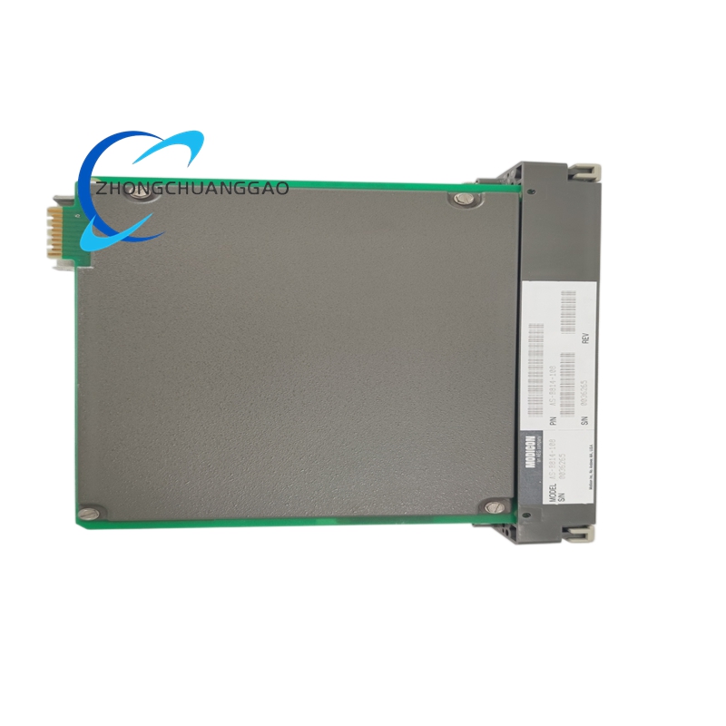
Product Name: Schneider Electric AS-B814-108 – Modicon M340 I/O Module, 8 Analog Inputs, 4–20 mA / 0–10 V
Product Overview:
The AS-B814-108 is an 8-channel analog input module for the Modicon M340 PLC. Accepts both current (4–20 mA) and voltage (0–10 V) signals with 16-bit resolution.
Description
Technical Specifications:
| Parameter | Value |
|---|---|
| Channels | 8 analog inputs |
| Input Type | 4–20 mA (2-wire) / 0–10 V (3-wire) |
| Resolution | 16-bit (65536 steps) |
| Accuracy (at 25°C) | ±0.1% of full scale |
| Sampling Rate | 1 ms per channel (all channels) |
| Isolation | 500 V AC (channel-to-channel, channel-to-bus) |
| Common Mode Rejection | 120 dB min |
| Power Consumption | 2.5 W (bus) |
| Operating Temperature | 0°C to +60°C |
| Mounting | DIN rail / M340 backplane |
| Standards | IEC 61131-2, CE, UL 508 |
Functional Features:
- Dual input range: 4–20 mA or 0–10 V (configurable per channel via DIP switch)
- 16-bit A/D converter per channel
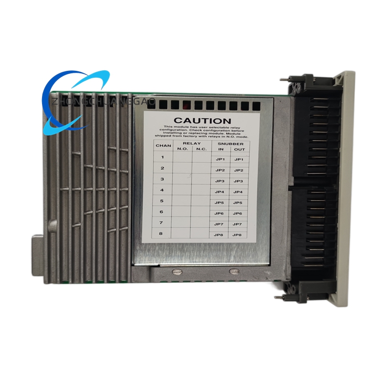
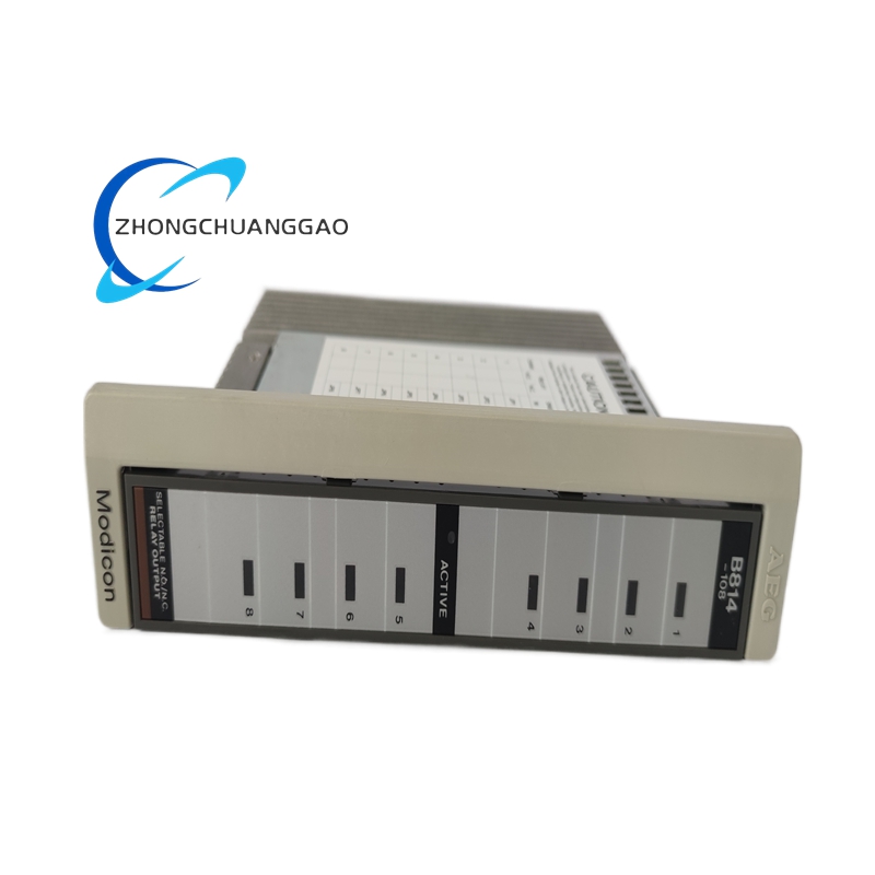
- Diagnostic LED per channel
- Cold-junction compensation for thermocouple use (with external module)
- Calibration via Unity Pro software
Material Composition:
- Housing: Polycarbonate (PC) – UL94 V-0
- PCB: FR-4, conformal coated
- Terminals: Spring-clip push-in
- Isolation: Optical isolation per channel
Structural Features:
- 40 mm module width
- DIP switches on front for range selection
- LED per channel for status/fault
- Backplane connector for M340
Working Principle:
Analog signal enters → signal conditioning (filtering, scaling) → 16-bit ADC converts → data sent via backplane to PLC CPU over Modbus/Ethernet. Isolation barrier prevents ground loops.
Advantages:
- 16-bit resolution for high-precision measurement
- Dual-range flexibility reduces spare parts
- Channel-level diagnostics simplify troubleshooting
Applicable Industries:
- Process control (chemical, water treatment)
- HVAC monitoring
- Energy management
- Food & beverage
Installation Requirements:
- Shielded twisted-pair cable for 4–20 mA signals
- Max cable length: 300 m (4–20 mA), 50 m (0–10 V)
- DIP switch must match sensor output type
Usage Notes:
- Never apply voltage to current input terminals (damages module)
- Calibrate zero and span via software before commissioning
- Keep analog cables separated from power cables (min 100 mm)
Reviews
There are no reviews yet.