
Product Short Description
Product Overview
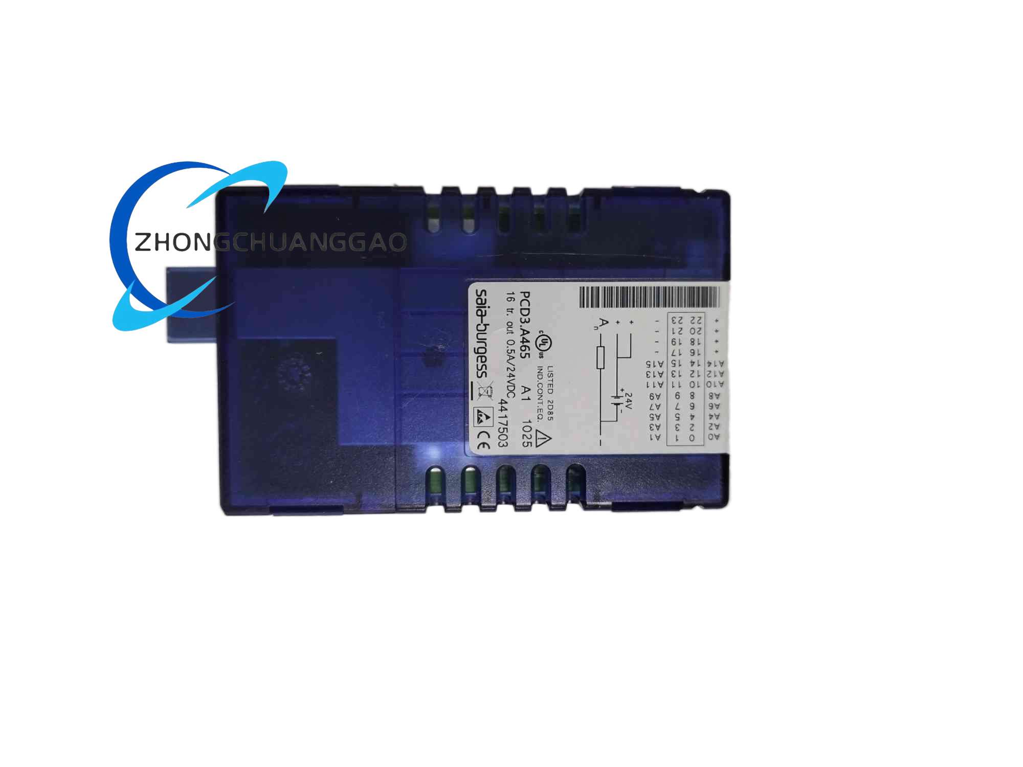
Description
Technical & Performance Parameters
- Total Analog Input Channels: 7 single-ended current input channels
- Supported Input Signal Range: 0…20mA, 4…20mA standard industrial current loop signals
- A/D Conversion Resolution: 12-bit, full scale value range 0~4095 digital counts
- LSB Minimum Resolution Step: 5μA per single digital bit
- Input Loop Internal Resistance: 120Ω with ±0.1% precision tolerance
- Full Scale Measurement Accuracy at 25°C Ambient Temperature: ±0.15%
- Repeatability Under Stable Test Conditions: ±0.05%
- Total Temperature Drift Error within 0°C~+55°C Operating Range: ±0.25%
- Single Channel A/D Conversion Time: ≤2ms
- Permanent Overcurrent Protection Threshold Per Channel: ±35mA
- Galvanic Isolation Specification: 500V AC isolation withstand between field input circuits and PCD3 internal bus, no inter-channel isolation
- Module Operating Power Supply: DC24V wide voltage input, power consumption less than 60mA
- Input EMC Surge Protection: Built-in bidirectional TVS transient suppression components for industrial electromagnetic interference suppression
- Filter Time Constant of Input Analog Filter Circuit: 12.4ms standard fixed value
Function Features
- Built-in multi-order RC analog low-pass filter circuit for each input channel, automatically suppressing high-frequency electromagnetic noise from long-distance field sensor wiring
- Independent open-loop fault detection logic for all 4-20mA current channels; the module automatically generates fault flag signals and transmits alarm data to the PCD3 CPU once sensor wiring breaks or current loop disconnection occurs
- On-board independent microcontroller chip undertakes signal scaling, moving average filtering and engineering unit conversion calculation tasks, completely offloading arithmetic computing pressure from the main PLC CPU
- Software configurable engineering value mapping function via PG5 programming software; users customize upper and lower limit corresponding physical values for each current input channel to match actual on-site measurement ranges
- Front panel dedicated LED status indicator for each analog input channel; separate light states to display normal signal input, over-range current signal and channel open-circuit fault conditions
- Support real-time upload of all 7-channel instantaneous current measurement values and channel fault status data to upper computer monitoring systems through the PCD3 system bus
Material Composition
- Outer Housing Shell: UL94-V0 flame retardant black ABS plastic with anti-static surface coating treatment
- Main Control Printed Circuit Board: Double-layer FR4 high temperature resistant fiberglass PCB, gold plating treatment on rear bus contact pins for long-term plugging anti-oxidation performance
- Signal Wiring Terminal Assembly: 14-pole pluggable spring cage quick wiring terminals, conductive terminals made of nickel-plated copper alloy, insulating outer shell made of high temperature resistant PA66 flame retardant plastic
- Isolation Components: High-speed linear optocoupler chips for galvanic isolation between field signal and internal bus circuits
- Precision Signal Conditioning Components: Low temperature drift metal film precision resistors and ceramic fixed capacitors for analog filter and current sampling circuits
- Internal Heat Conduction Components: Thin copper foil heat conduction patches attached to optocoupler and signal conditioning chips for passive heat dissipation
Structural Characteristics
- Installation Mounting Form: Standard 35mm EN60715 DIN top hat rail clamping installation
- Overall Module External Dimensions: Width 52mm, Height 86mm, Depth 70mm
- Front Panel Layout: 7 independent LED indicator lamps corresponding to each analog input channel, transparent detachable plastic dust cover covering all spring wiring terminals to prevent dust accumulation and accidental short-circuit faults
- Internal Circuit Zoning Layout: Front area of PCB arranges analog input signal conditioning circuits; rear area arranges galvanic isolation optocoupler circuits and PCD3 expansion bus interface circuits; internal shielding partition separates analog weak signal circuits and digital bus circuits to eliminate crosstalk interference
- Terminal Partition Layout: All 7 analog input signal terminals concentrated on upper terminal row, DC24V module power supply terminals and grounding shielding terminals arranged at the rightmost position of the terminal block to realize physical separation between power supply circuits and weak analog signal circuits
- Rear Bus Connection Structure: Rear side of the module is equipped with gold finger bus connector, directly inserted into the slot of PCD3 series aluminum alloy backplane rack to complete high-speed data communication connection with the PLC CPU
Working Principle
- Analog Current Signal Sampling Process
Field 2-wire industrial current transmitters output 4-20mA or 0-20mA current loop signals to the module input terminals. The current signal flows through the built-in 120Ω precision sampling resistor inside the module, converting current variation into proportional analog voltage signals. The converted voltage signal first passes through multi-order RC low-pass filter circuit to eliminate high-frequency industrial electromagnetic interference noise, then enters linear optocoupler galvanic isolation circuit to cut off electrical connection between field equipment and PLC internal digital circuits, avoiding ground loop induced measurement distortion.
- A/D Conversion & Data Transmission Process
The isolated analog voltage signal is sent to the built-in 12-bit high precision A/D conversion chip, converting continuous analog electrical signals into discrete digital count values. The on-board microcontroller reads digital conversion data, executes pre-programmed moving average filtering and engineering unit scaling algorithms, then stores processed measurement data into local module buffer memory. The buffer data is transmitted to the PCD3 main CPU controller through the rear expansion bus at fixed sampling cycles, and the CPU stores all channel measurement values into dedicated analog input image memory area for user control program logic judgment and closed-loop regulation calculation.
- Channel Fault Diagnosis Mechanism
Independent impedance detection circuits continuously monitor the loop impedance of each 4-20mA current input channel. When sensor wiring breaks or the current loop opens, the loop impedance exceeds the preset threshold value, the module generates a dedicated fault flag digital signal, stores fault location information in buffer memory, and synchronously triggers the corresponding channel LED fault indicator lamp on the front panel. The fault data is uploaded to the PLC CPU in the next bus data transmission cycle for alarm recording and linkage safety control logic execution.
Installation Requirements
- DIN Rail Mounting Standard
Fix the 35mm standard DIN top hat rail horizontally on a flat metal electrical cabinet mounting plate with M4 stainless steel screws, ensuring the mounting surface maintains complete flatness without bending deformation. Clamp the bottom clamping buckle of the PCD3.W315 module onto the DIN rail, press the upper housing to lock the module into fixed horizontal installation position, no vertical upside-down installation is allowed.
- Cabinet Internal Heat Dissipation Space Clearance
Maintain minimum vertical clearance of 25mm above and below the module housing to form natural vertical air convection heat dissipation channels; reserve minimum horizontal clearance of 8mm between the PCD3.W315 module and adjacent digital I/O expansion modules installed on the same PCD3 backplane rack to avoid mutual heat accumulation between multiple modules under full load operation.
- Analog Signal Wiring Specification
All field current sensor signal wiring must adopt shielded twisted pair cables with 0.5mm² copper conductor cross-section. The shielding layer of each signal cable is single-end grounded at the internal cabinet grounding busbar, double-end grounding of shielding layers is strictly prohibited to prevent ground loop current generation leading to signal measurement distortion. The stripped wire length of all wiring conductors inserted into spring cage terminals is fixed at 6mm to guarantee complete contact between conductor and terminal conductive spring without loose contact heating faults.
- Operating Environment Temperature & Humidity Limits
Continuous stable operating ambient temperature range: 0°C ~ +55°C; short-term peak temperature within 1 hour shall not exceed +60°C. Storage and transportation environment temperature range: -25°C ~ +70°C. Operating relative humidity range: 5% ~ 95%, all installation environments must maintain non-condensing moisture conditions; installation inside fully sealed high-temperature electrical cabinets must install independent cabinet cooling fans to control internal cabinet temperature not exceeding the upper operating temperature limit.
- Protective Grounding Installation Rules
Connect the dedicated shielding grounding terminal on the module terminal block to the copper grounding busbar inside the electrical cabinet with a 1.5mm² cross-section copper grounding wire, the total grounding resistance of the factory industrial grounding network shall not exceed 4Ω to eliminate electrostatic charge accumulation and external electromagnetic interference noise.
Application Scenarios
- Building HVAC Central Air Conditioning Automation Systems: Chilled water pipeline flow transmitter signal collection, air handling unit temperature and humidity transmitter data acquisition, cooling tower liquid level current sensor signal monitoring
- Industrial Water Treatment Process Control Equipment: Sewage tank PH value transmitter current signal sampling, clean water pipeline flow meter data collection, dosing tank liquid level transmitter signal monitoring
- Light Chemical & Food Fermentation Production Lines: Fermentation tank temperature, pressure and dissolved oxygen 4-20mA transmitter signal collection, pipeline material flow monitoring
- Municipal Public Facility Monitoring Systems: Urban heating pipe network heat exchange station temperature and flow sensor data acquisition, urban water supply pump station liquid level monitoring
- Small Energy Consumption Monitoring Terminals: Solar photovoltaic power station irradiance and temperature current transmitter signal collection, industrial boiler flue gas temperature and pressure sensor data sampling
Usage Precautions
- Strictly prohibit connecting AC voltage signals of any specification to the analog input terminals of the module; all input terminals only support DC low voltage current loop signals, AC signal input will permanently damage the internal optocoupler isolation and A/D conversion circuits.
- When wiring 2-wire current transmitters connected to the module input channels, strictly follow the positive and negative polarity marking on the terminal block; reverse polarity wiring will lead to complete loss of measurement signals and trigger channel open-circuit fault alarm status.
- Hot plugging or removal of the PCD3.W315 module is forbidden when the entire PCD3 PLC system is powered on; the DC24V power supply of the entire backplane rack must be completely cut off before installing, replacing or removing the module to avoid overcurrent breakdown damage to the rear expansion bus drive chip.
- The internal analog signal conditioning and A/D conversion circuits of the module are extremely sensitive to dust and moisture accumulation; clean the front panel transparent terminal dust cover every 3 months of continuous operation with a dry anti-static soft cloth, prohibit using water, alcohol or chemical solvent liquid to wipe the module housing and internal circuit components to prevent liquid infiltration causing short-circuit faults.
- When configuring engineering value mapping parameters for each analog input channel via PG5 programming software, the upper and lower limit physical values set must fully match the actual measuring range of the field current transmitters to avoid incorrect conversion of measured physical values in the PLC control program.
- If the module is stored idle for more than 6 months without power supply operation, store the module in a sealed dry storage box with temperature maintained between -10°C and +40°C; before reinstallation and commissioning after long-term storage, execute full-channel zero point and full-scale calibration operation through PG5 software to restore original factory signal conversion measurement accuracy.
- When installing multiple analog input modules including PCD3.W315 on the same PCD3 aluminum alloy backplane rack, arrange all analog signal modules on the left side of the rack, place all digital input/output expansion modules on the right side of the rack to minimize digital high-speed pulse signal electromagnetic interference to weak analog measurement signals.
Reviews
There are no reviews yet.