
Product Short Description
Product Brief Introduction
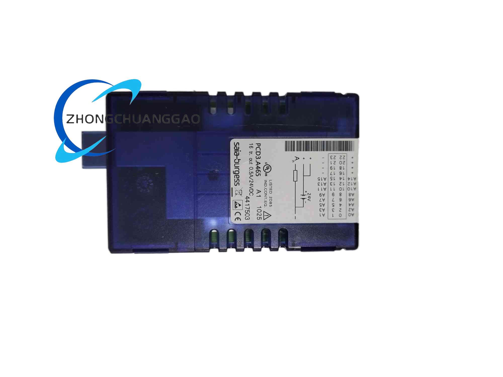
PCD3.A465 is a dedicated digital output expansion module belonging to SAIA PCD3 modular PLC platform, designed to expand large quantities of discrete switching output points for PCD3.M series CPU base units. It connects to CPU via internal S-Bus system bus, supporting hot-swap module replacement under system power-on state without shutting down the entire automation stationManualsLib
Description
Core Technical Specifications
- Channel Configuration
- Total Digital Output Channels: 16 independent Form C mechanical relay output points
- Single Channel Rated Load: Max 5 A resistive load, max 2 A inductive AC load
- Output Isolation: Each relay channel achieves complete galvanic isolation between module internal bus circuit and field actuator wiring, isolation withstand voltage 2500 V AC for 1 minute
- Bus Interface Parameters
- System Bus Type: S-Bus high-speed internal expansion bus
- Bus Communication Rate: 4 Mbps real-time data transmission
- Max Expansion Module Quantity: Up to 64 PCD3 series expansion modules connectable to single PCD3 CPU base unit
- Power Supply Parameters
- Module Internal Logic Power: Supplied via S-Bus expansion bus from CPU base unit, no separate 24 V DC logic power wiring required
- Field Actuator Output Power: External 24 V DC or 230 V AC power supply connected to module common terminal blocks, separate power loop independent of controller logic power
- Module Max Power Consumption (Logic Circuit): 1.2 W
- Environmental & Mechanical Parameters
- Operating Temperature: 0 °C ~ +55 °C (when mounted in middle cabinet positions); 0 °C ~ +40 °C for fully loaded multi-module rack with poor air circulation
- Storage Temperature: -40 °C ~ +85 °C
- Protection Class: IP20
- Dimensions (W × H × D): 30 mm × 126 mm × 85 mm
- Net Weight: 0.18 kg
- Certifications: CE, UL
Function Features
- 16 independent isolated relay output channels, each channel equipped with dedicated LED status indicator light (red light lit when relay contact closed, dark when open)
- S-Bus hot-swap support; module can be inserted or removed from DIN rail expansion rack while CPU base unit remains powered, system automatically re-scans module address without full station reboot
- Built-in overcurrent short-circuit protection for each output channel; short-circuit at field actuator wiring triggers channel self-locking protection, corresponding LED flashes alarm, only recoverable after power cycle of module external output power
- Automatic module address identification via S-Bus; no manual DIP switch address setting required, CPU automatically allocates I/O mapping address after module physical installation
- Over-temperature protection circuit; internal temperature sensor monitors relay heat accumulation, automatically cuts off all output channels when internal temperature exceeds 70 °C to prevent plastic housing melting fire risk
- Compatible with full PCD3 CPU series including M5540, M6340 base units, unified PG5 engineering software I/O configuration programming
Working Principle
The PCD3.A465 communicates with the main CPU through S-Bus differential signal bus. The CPU transmits target output state data of all 16 channels to the module at each PLC scan cycle. The module’s on-board auxiliary microcontroller receives bus data, decodes each channel’s switch command, and drives corresponding mechanical relay coil power supply circuits to close or open contact points connected to field actuators. Each relay channel integrates independent current sampling resistance and temperature sensing chip. When output channel current exceeds rated threshold or internal relay temperature rises abnormally, auxiliary microcontroller immediately cuts relay coil power supply and sends fault diagnostic code back to main CPU via S-Bus for upper monitoring system fault display. All bus signal circuits and field output power circuits are separated by optocoupler isolation components to eliminate field high-voltage interference feeding back into CPU mainboard circuits.
Material Composition & Structural Characteristics
- Housing: Flame-retardant UL94-V0 ABS plastic, modular narrow-width slim design for high-density I/O rack layout
- Circuit Board: FR4 double-layer industrial PCB, all relay drive circuits equipped with surge absorption capacitors
- Terminal Blocks: Two groups of spring cage screw terminals, separate terminals for common output power and each independent channel wiring; terminal blocks are detachable for pre-wiring off-cabinet
- Bus Connection Structure: Built-in backplane S-Bus gold-plated spring contact at module side edge; multiple modules dock side-by-side to form continuous expansion bus without external bus cable wiring
- DIN Rail Mount: Integrated plastic clamping buckle on module bottom, quick lock/unlock design for fast module replacement during maintenance
Installation Requirements
- Mounting: Install sequentially on 35 mm DIN rail expansion rack adjacent to PCD3 CPU base unit, modules dock side edge-to-side to complete S-Bus bus connection
- Temperature Clearance: Minimum 30 mm vertical air gap above and below expansion rack; install cabinet exhaust fan when more than 8 PCD3.A465 modules are mounted in single rack to reduce heat accumulation
- Wiring Separation: Separate field actuator high-current output wiring (230 V AC) from low-voltage S-Bus and CPU power wiring, maintain minimum 10 cm cable routing separation distance to avoid electromagnetic interference
- Grounding: Connect module cabinet mounting DIN rail to protective earth busbar with copper ground wire to suppress static electricity accumulation on module plastic housing
- Hot-Swap Operation Rule: When replacing module under power-on state, first disconnect external field output power supply of target module before pulling module off DIN rail to avoid live contact sparking damage to bus gold-plated contacts
Application Scenarios
- Building Automation Large I/O Expansion: Multi-floor lighting group control, multiple HVAC air damper actuator switching control, water supply pump group automatic switching
- Packaging & Conveying Machinery: Multi-station cylinder solenoid valve output control, sorting conveyor baffle actuator switching, palletizer mechanical arm auxiliary action output
- Water & Wastewater Treatment Plant: Multi-group dosing pump interlock output, aeration fan group sequential start-stop control, drain gate actuator switching
- Central Air Conditioning System: Chiller unit auxiliary valve control, cooling tower fan group automatic load adjustment output
Operation Precautions
- Never connect voltage exceeding 250 V AC to relay output terminals; overvoltage will breakdown internal isolation components and damage module bus circuit
- Inductive loads (solenoid valves, AC contactors) must install parallel surge suppression diode (DC load) or RC absorption circuit (AC load) at actuator wiring terminals to absorb inductive reverse electromotive force
- Avoid continuous long-time full-load operation of all 16 output channels simultaneously; long-term full load causes excessive heat accumulation and accelerates relay contact wear aging
- When executing hot-swap replacement, strictly follow power disconnection sequence; live disconnection will scratch gold-plated S-Bus contacts and cause permanent bus communication failure
- Conduct semi-annual maintenance inspection: check terminal screw tightness, wipe LED indicator surface dust with dry cloth, test relay channel action function via PG5 software diagnostic tool
Reviews
There are no reviews yet.