
Product Short Description
Product Overview
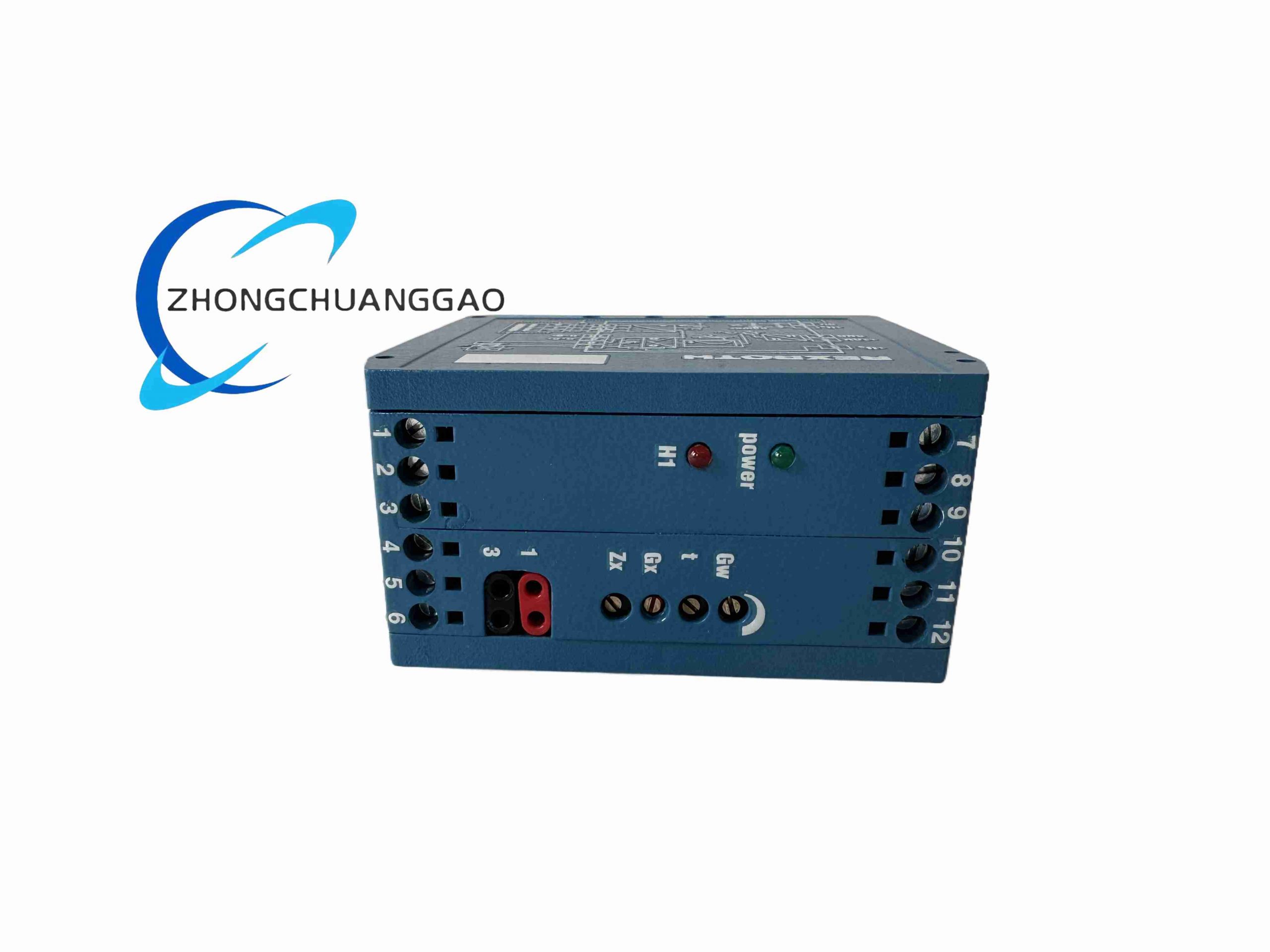
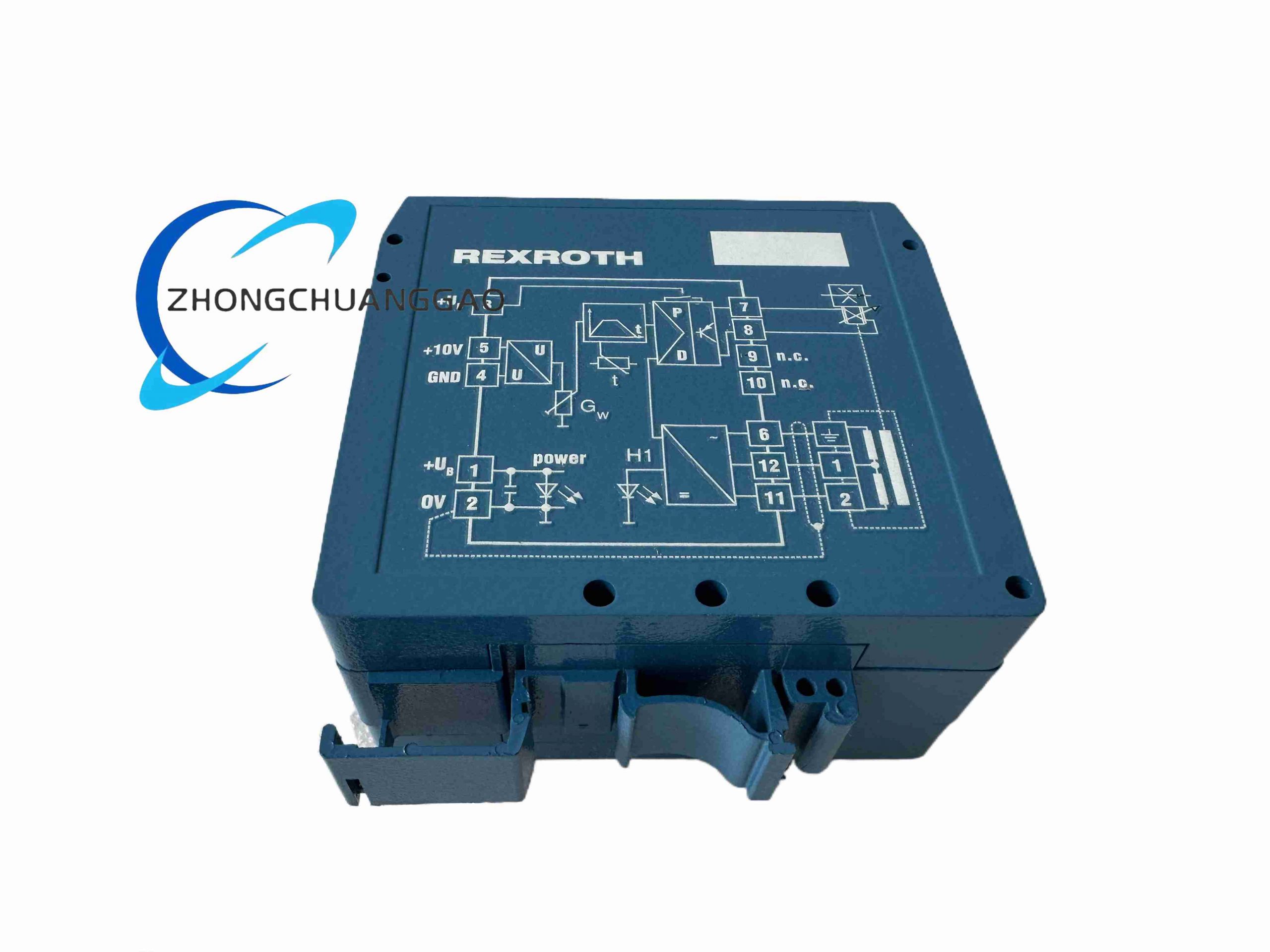
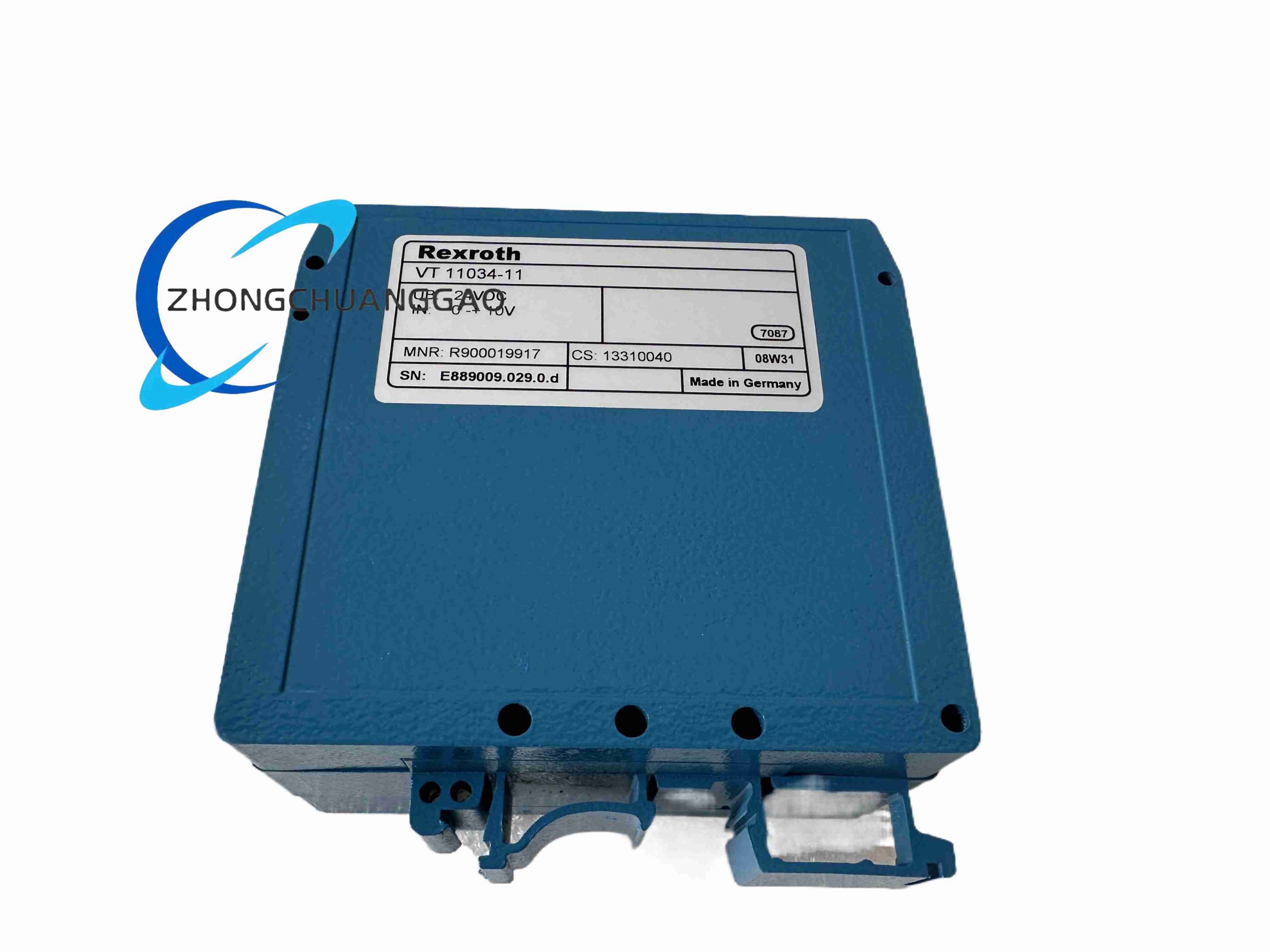
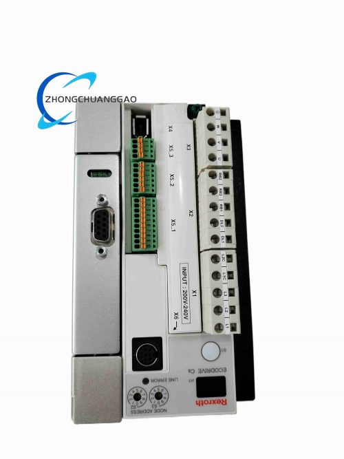
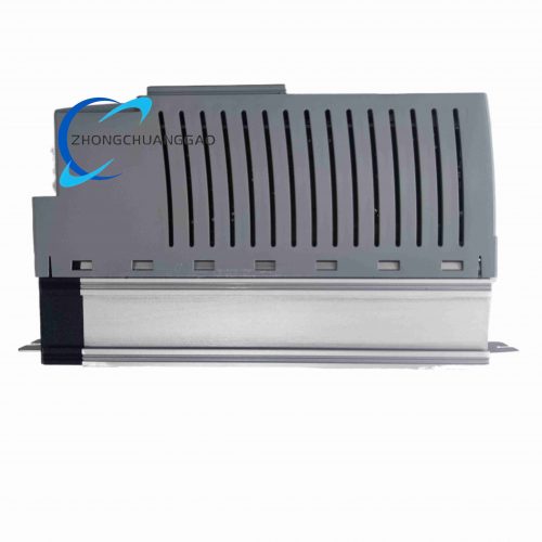
VT-11034-11 is a compact rack-mount analog proportional valve amplifier developed by Bosch Rexroth, specially designed to drive single-coil proportional directional control valves in industrial hydraulic systems. It converts standard 0–10 VDC or 4–20 mA analog command signals from PLC, vibration monitoring systems and process controllers into regulated proportional current output for valve solenoids. Built-in ramp generation, dither oscillation and fault diagnosis circuits ensure smooth hydraulic flow regulation and long service life of hydraulic valves, widely matched with Rexroth 4WRE, 4WREE series proportional directional valves.
Description
Core Technical Specifications
- Control Channel: Single independent proportional solenoid drive channel
- Input Command Signal Options: 0–10 VDC voltage signal, 4–20 mA current signal (software jumper selectable)
- Rated Solenoid Output Current: 0–2.5 A continuous adjustable proportional output
- Dither Frequency: Fixed 200 Hz high-frequency dither signal to eliminate valve spool static friction hysteresis
- Ramp Time Adjustment: 0.05 s to 10 s adjustable rising/falling ramp via front panel potentiometers
- Power Supply Input: 24 VDC ±10% industrial cabinet power supply, maximum power consumption 45 W
- Fault Detection Functions: Solenoid open-circuit detection, coil short-circuit protection, over-temperature alarm
- Operating Temperature Range: -20°C ~ +70°C cabinet ambient temperature
- Mounting Standard: DIN rail 35 mm standard snap-on mounting structure
- Galvanic Isolation: 1000 Vrms isolation between command signal input and solenoid power output circuit
- Linearity Deviation: ≤0.5% full scale proportional control error
- Weight: 320 g per single amplifier unit
Functional Features
- Built-in adjustable acceleration/deceleration ramp function to suppress hydraulic shock and pipeline pressure impact during valve switching
- 200 Hz constant dither output eliminates static friction hysteresis of valve spools, improving low-flow control precision
- Dual-mode analog input compatibility supports all mainstream industrial PLC and machinery monitoring system signal standards
- Hardware-level overcurrent, short-circuit and over-temperature protection automatically cuts solenoid drive output to avoid component burnout
- Front-panel adjustable potentiometers for zero offset, gain and ramp time without dedicated configuration software
- Isolated signal input circuit effectively eliminates ground loop interference between control cabinet and hydraulic station
- Compact DIN rail mounting design allows dense layout inside small hydraulic control cabinets
- Front panel LED status indicators for power supply, active drive output and coil fault warning for rapid on-site troubleshooting
Working Principle
PLC or vibration monitoring equipment transmits analog command signal (0–10 VDC / 4–20 mA) to the isolated input terminal of VT-11034-11. The internal analog conditioning circuit converts the command signal into a reference voltage value, adjustable gain and zero-offset circuits calibrate the target control curve. A ramp generator smooths sudden signal changes to avoid hydraulic impact, and a superimposed 200 Hz dither signal is added to the proportional drive current. The power amplification circuit outputs stable regulated current to the proportional valve solenoid; the magnetic force generated by the solenoid pushes the valve spool to adjust hydraulic flow and pressure proportionally. Auxiliary monitoring circuit tracks solenoid coil current and module internal temperature; abnormal parameters trigger fault LED indication and cut drive current for self-protection.
Material & Structural Characteristics
- Main Circuit Board: Low-loss FR4 PCB with wide-temperature industrial power components
- Housing Shell: Flame-retardant black ABS plastic, IP20 front panel dust protection
- Adjustment Components: Sealed metal trimming potentiometers with rubber dust caps to prevent oil mist contamination
- Terminal Blocks: PA66 flame-resistant plastic, tin-plated copper spring screw terminals for control wiring and solenoid connection
- DIN Rail Buckle: Reinforced glass fiber plastic anti-vibration snap structure for hydraulic station vibration environments
- Power Drive Components: High-efficiency MOSFET power tubes with integrated miniature heat sinks for continuous high-current operation
Installation Requirements
- Snap the amplifier firmly onto standard 35 mm DIN rail inside sealed hydraulic control cabinets; ensure no loose sliding under mechanical vibration
- Separate low-level analog command signal cables and high-current solenoid drive cables with a minimum spacing of 8 cm; avoid parallel wiring
- Connect the cabinet earth terminal to the hydraulic station unified grounding grid using a 2.5 mm² copper wire
- Reserve at least 10 mm vertical clearance above and below each VT-11034-11 unit for heat dissipation; do not stack multiple amplifiers tightly
- Solenoid connecting wires must adopt shielded twisted pair cables with a cross-section of no less than 1.0 mm² to reduce drive signal attenuation
- In high-humidity hydraulic workshops, install cabinet heating strips to prevent condensation dripping on the amplifier circuit board
Application Scenarios
- Steel mill rolling machine hydraulic proportional flow control matched with vibration monitoring interlock logic
- Plastic injection molding machine hydraulic proportional directional valve speed and pressure regulation systems
- Hydraulic test bench for turbine and compressor component flow adjustment control
- Offshore platform hydraulic actuator proportional drive control cabinets
- Metal stamping press hydraulic feed and clamping speed adjustment systems
- Wind turbine pitch control hydraulic station proportional valve drive units
Operation & Maintenance Precautions
- Do not connect solenoid coils with rated current exceeding 2.5 A; sustained overload will damage internal power MOSFET tubes
- Cover all front panel potentiometer rubber caps after calibration to block hydraulic oil mist and dust intrusion
- Inspect solenoid wiring insulation quarterly; cracked insulation leads to short-circuit faults and frequent amplifier protection shutdown
- Avoid mounting the amplifier near hydraulic power units with strong heat radiation to prevent over-temperature triggering
- Reset zero offset and gain potentiometers every 12 months if hydraulic control precision drift is observed
- If the fault LED stays lit after wiring inspection, replace the proportional solenoid coil first before replacing the amplifier unit
Reviews
There are no reviews yet.