
Product Short Description
Product Overview
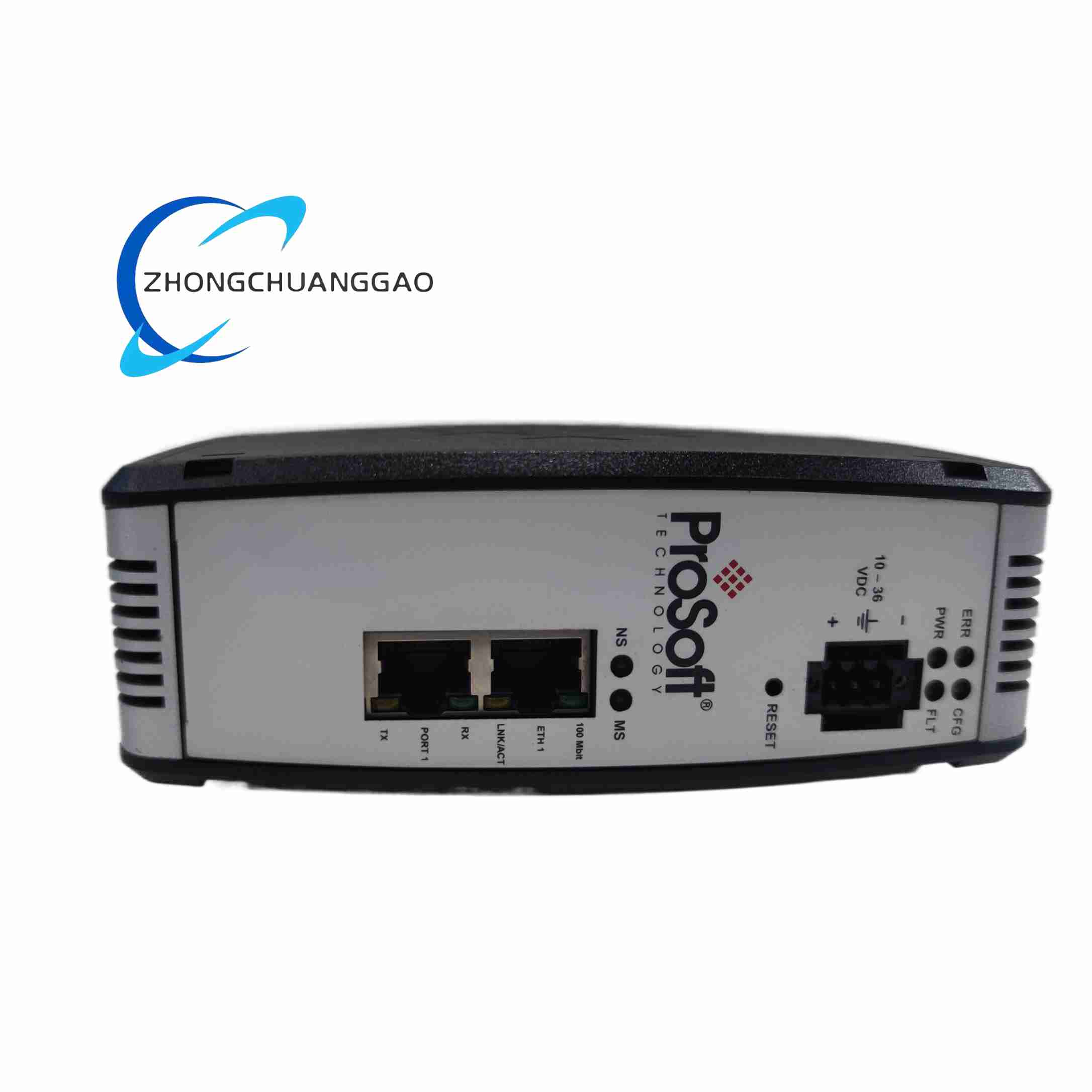
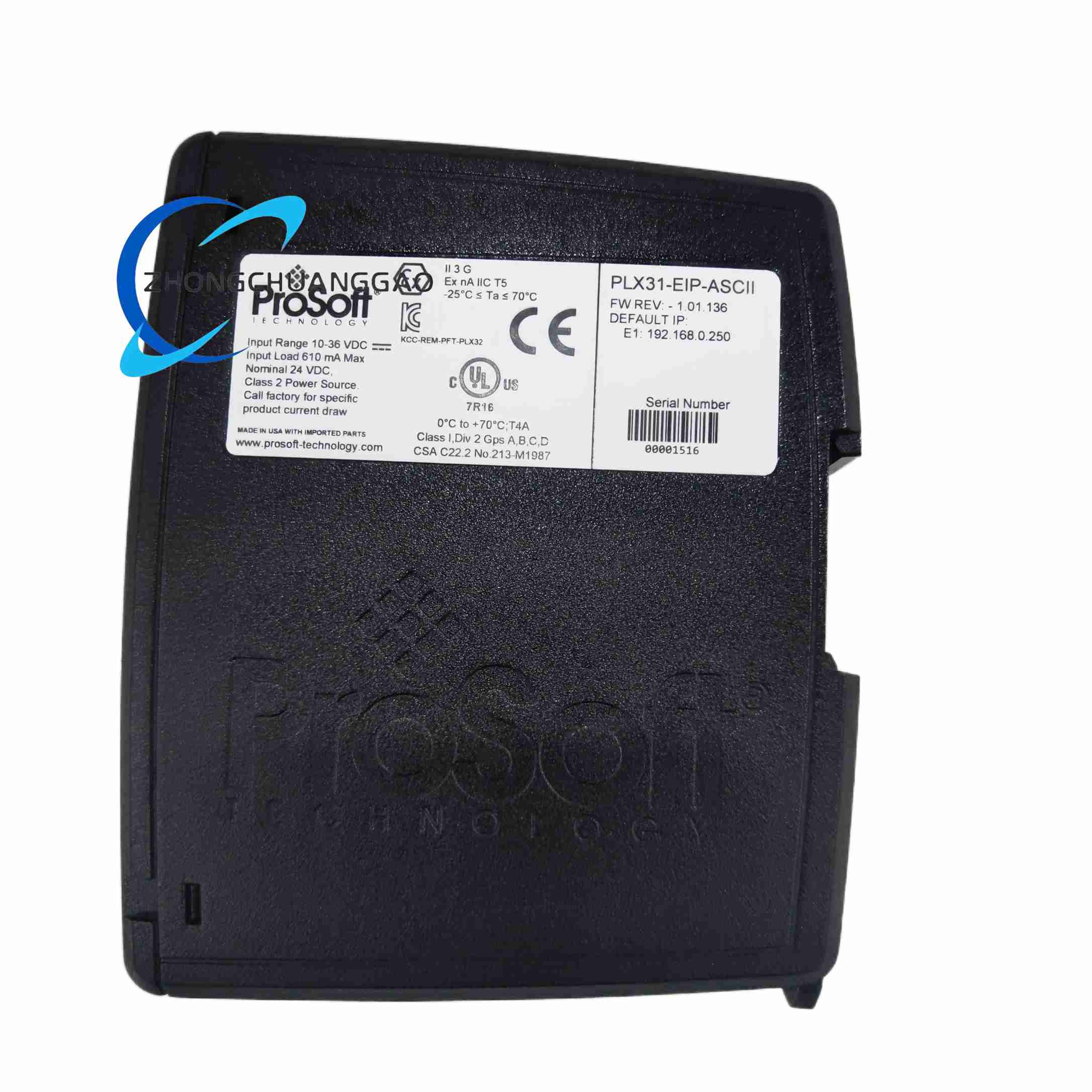
The PLX31-EIP-ASCII is compact DIN rail-mounted protocol conversion hardware developed by ProSoft Technology. It builds transparent bidirectional data transmission channels between Rockwell EtherNet/IP PLC control networks and serial ASCII field devices. No complex custom PLC programming is required to realize data collection and command issuing between different communication standards.
Description
Power System Parameters
Nominal input voltage stands at 24 VDC, with a wide universal input range spanning 10 to 36 VDC.
Rated operating current reaches roughly 300mA under 24VDC operating condition.
The power terminal adopts three-terminal layout including positive pole, negative pole and protective ground.
Equipped with one 10/100 Mbps auto-adaptive industrial RJ45 Ethernet port.
Compatible with two mainstream EtherNet/IP transmission modes including implicit I/O connection and explicit message transmission.
The gateway supports up to 5 simultaneous server-side connection channels.
Each single data frame allows a maximum transmission payload of 255 ASCII characters.
Pre-installed EDS add-on profile inside hardware enables seamless matching and configuration with Rockwell Studio 5000 programming software.
Single multi-mode serial port integrates RS232 and RS485 dual signal standards.
All serial communication parameters support full independent configuration:
Baud rate adjustable from 300 bps to 115200 bps
Data bit counts optional 7 or 8
Stop bits selectable as 1 or 2
Parity modes including None, Odd and Even
The hardware supports customized start and stop delimiter recognition, which can intercept complete ASCII data frames transmitted from peripheral instruments.
Overall outer dimensions measure 100mm height × 72mm width × 38mm depth.
The module is designed for installation on standard 35mm DIN rails with snap-on fixing structure.
The outer shell adopts high-strength flame-retardant ABS industrial plastic material.
The front panel reaches IP30 dustproof protection grade.
Multiple status indicator lights are arranged on the front panel:
Power status indicator
Ethernet link and activity indicator
Serial sending and receiving indicator
Module fault alarm indicator
Normal continuous operating temperature range covers -20°C to +65°C.
The allowable storage temperature range extends from -40°C to +85°C.
Adaptable relative humidity environment ranges from 5% to 95%, non-condensing.
The whole module passes industrial vibration testing standards specified by IEC 60068-2-6 to resist mechanical vibration interference generated by factory production equipment.
Dual-way configurable client and server communication mode
Engineers can freely set the gateway as an EtherNet/IP client to actively read real-time data from ASCII serial devices.
Or configure it as an EtherNet/IP server to receive control commands sent from Rockwell ControlLogix and CompactLogix series PLCs.
Flexible mode switching fully adapts to different control logic frameworks of on-site production lines.
Multiple independent I/O connection channels support customizable RPI packet transmission intervals.
Critical real-time control data can be assigned shorter transmission cycles to guarantee response speed.
Low-priority equipment monitoring data adopts longer transmission intervals to reduce occupation of industrial Ethernet bandwidth resources.
A standard microSD card slot is reserved on the front panel of the module.
All core configuration information can be completely stored into the SD card:
Bidirectional data mapping rules
Serial communication frame identification parameters
Network IP address settings
When on-site gateway hardware is damaged and needs to be replaced, backup configuration file can be directly imported through SD card without repeated manual parameter debugging.
Support matching with PC-side ProSoft Discovery Service management software.
The tool can automatically scan all PLX31 series gateway devices distributed in the factory local area network.
Maintenance personnel can modify the default IP address of the gateway without adjusting the subnet of the configuration computer.
Greatly simplifies batch network deployment work of multiple communication gateways in different production workshops.
Built-in hardware password locking function prevents irrelevant staff from unauthorized modification of communication mapping parameters.
IP address filtering function only allows designated EtherNet/IP PLC equipment to establish data connection with the gateway.
Internal CRC32 full data frame verification mechanism effectively filters garbled frames caused by electromagnetic interference in industrial sites to ensure complete and accurate data transmission.
Power-on initialization and self-inspection stage
After the DC power supply is connected and powered on, the embedded industrial-grade processor inside the gateway reads all pre-stored communication configuration files stored in the internal flash memory chip.
The system sequentially completes initialization work:
Ethernet MAC address
IP subnet information
Serial port baud rate and parity parameters
User-defined ASCII frame start and stop identifier rules
After finishing full hardware circuit self-test, all status indicator lights will keep steady green light to indicate that the gateway has entered the normal data communication standby state.
On the EtherNet/IP network side
The RJ45 Ethernet port continuously receives industrial control data frames transmitted from Rockwell PLC equipment.
The built-in hardware CRC verification circuit quickly judges the integrity of data frames.
Filters out damaged noise frames generated by electromagnetic interference.
Extracts valid application data units that can be identified by the protocol parsing engine.
The RS232/RS485 interface receives raw ASCII text data sent by on-site measuring instruments and peripheral equipment.
The internal optocoupler isolation circuit isolates high-voltage industrial field interference signals.
Converts differential serial signals into single-ended digital signals.
Intercepts complete independent ASCII data frames according to the pre-set start and stop character identifiers.
Two independent high-speed protocol parsing engines run synchronously inside the gateway.
All bidirectional data transmission follows the pre-configured mapping table rules to complete protocol conversion and data repackaging work.
Control command data transmitted from the EtherNet/IP PLC side will be split, aligned and reorganized into standard ASCII text data frames matching the communication rules of serial peripheral equipment.
Then transmitted to the terminal measuring instrument through the serial port.
Real-time feedback data uploaded by ASCII serial equipment will be segmented, sorted and repackaged into EtherNet/IP standard I/O data blocks matching the tag memory address of Rockwell PLC.
Then uploaded to the upper industrial control network through the Ethernet port.
The gateway maintains uninterrupted cyclic bidirectional data exchange operation.
Built-in frame timeout retransmission logic can automatically resend data frames when temporary network fluctuation occurs in the factory site.
Once the data communication link on either the Ethernet side or serial port side is disconnected:
The corresponding port activity indicator will flash orange light
The module fault indicator will continuously flash red light to remind on-site maintenance personnel of abnormal communication faults
All fault codes and accurate fault occurrence time will be automatically stored in the internal flash memory of the module for later fault analysis and troubleshooting.
Mechanical installation standard specifications
The module must be horizontally installed on a standard 35mm DIN rail inside a fully enclosed industrial electrical control cabinet.
Vertical upside-down installation or inclined side installation is strictly prohibited, which will cause heat accumulation inside the module and accelerate aging of internal electronic components.
A minimum of 20mm vertical empty space should be kept above and below the gateway module to ensure natural air circulation heat dissipation.
Heat-generating electrical components such as AC contactors and high-power switching power supplies cannot be installed within a horizontal distance of 10cm from the gateway shell to avoid high-temperature radiation affecting the stable operation of the communication module.
The power supply and serial communication terminals on the front panel adopt detachable spring-type wiring terminal structure.
All wiring work can be completed without removing the whole module from the DIN rail, which greatly facilitates daily on-site wiring maintenance and equipment replacement work.
Power supply wiring
Shielded twisted pair cables are required for power supply wiring.
The protective ground terminal on the gateway must be firmly connected to the main protective ground bus bar of the electrical cabinet, which can effectively suppress electromagnetic interference generated by high-power equipment in the control cabinet.
Industrial CAT5e fully shielded twisted pair Ethernet cables must be used for all Ethernet connection wiring.
The metal shielding shell of the RJ45 connector needs to be connected to the cabinet ground wire to eliminate signal crosstalk between different communication lines.
For RS485 long-distance serial communication wiring, shielded twisted pair cables must be adopted.
The maximum stable transmission distance can reach 1200 meters under the baud rate of 9600bps.
The maximum transmission distance of RS232 short-distance communication is limited to 15 meters.
Outer shell split panel design
The whole module adopts an integrated integral flame-retardant ABS plastic shell.
The front panel adopts a split design to separate the wiring terminal operation area and the internal circuit board sealing compartment.
Prevents dust generated by wiring from entering the precision communication circuit inside the shell.
Independent metal shielding partition plates are arranged inside the shell to separate the internal EtherNet/IP protocol processing circuit board and the ASCII serial signal processing circuit board.
Completely eliminates electromagnetic signal crosstalk between different signal channels inside the module shell.
The front panel is equipped with an independent array of status indicator lights.
Separately display power supply working state, dual-channel communication link activity and module overall fault alarm state.
Maintenance personnel can quickly judge the real-time operating state of the gateway without connecting professional configuration software.
Food and beverage automated production lines
Realize data interconnection between Rockwell EtherNet/IP main control PLC and on-site production line equipment:
Weighing scales
Barcode scanning equipment
Thermal label printers
Liquid level monitoring ASCII sensors
Complete automatic uploading of weighing batch data, full-process product barcode traceability recording and automatic storage of filling production parameter information.
Connect the central EtherNet/IP SCADA monitoring network with field flow meters, pressure ASCII transmitters and crude oil sampling detection equipment.
Realize remote real-time monitoring of pipeline pressure, flow rate and liquid density data.
Connect main Rockwell control PLC with water quality pH/ORP ASCII analyzers, water tank liquid level sensors and power station auxiliary equipment data terminals.
Realize automatic water quality parameter adjustment and equipment operating status monitoring.
Assembly workstation barcode scanners, product testing ASCII data acquisition instruments, industrial marking printers.
Realize automatic product testing data upload to PLC production control program.
Reviews
There are no reviews yet.