
Product Short Description
Product Overview
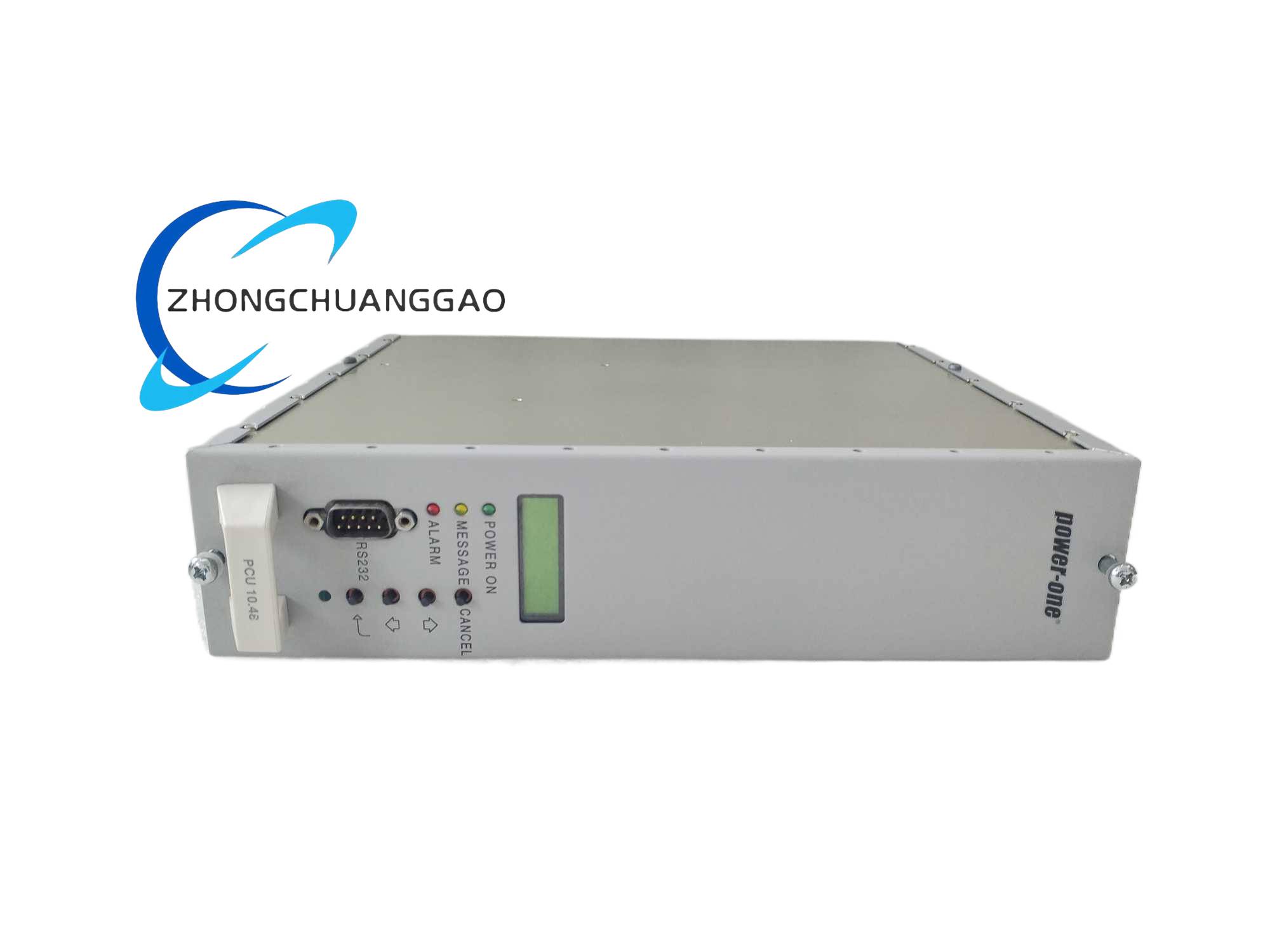
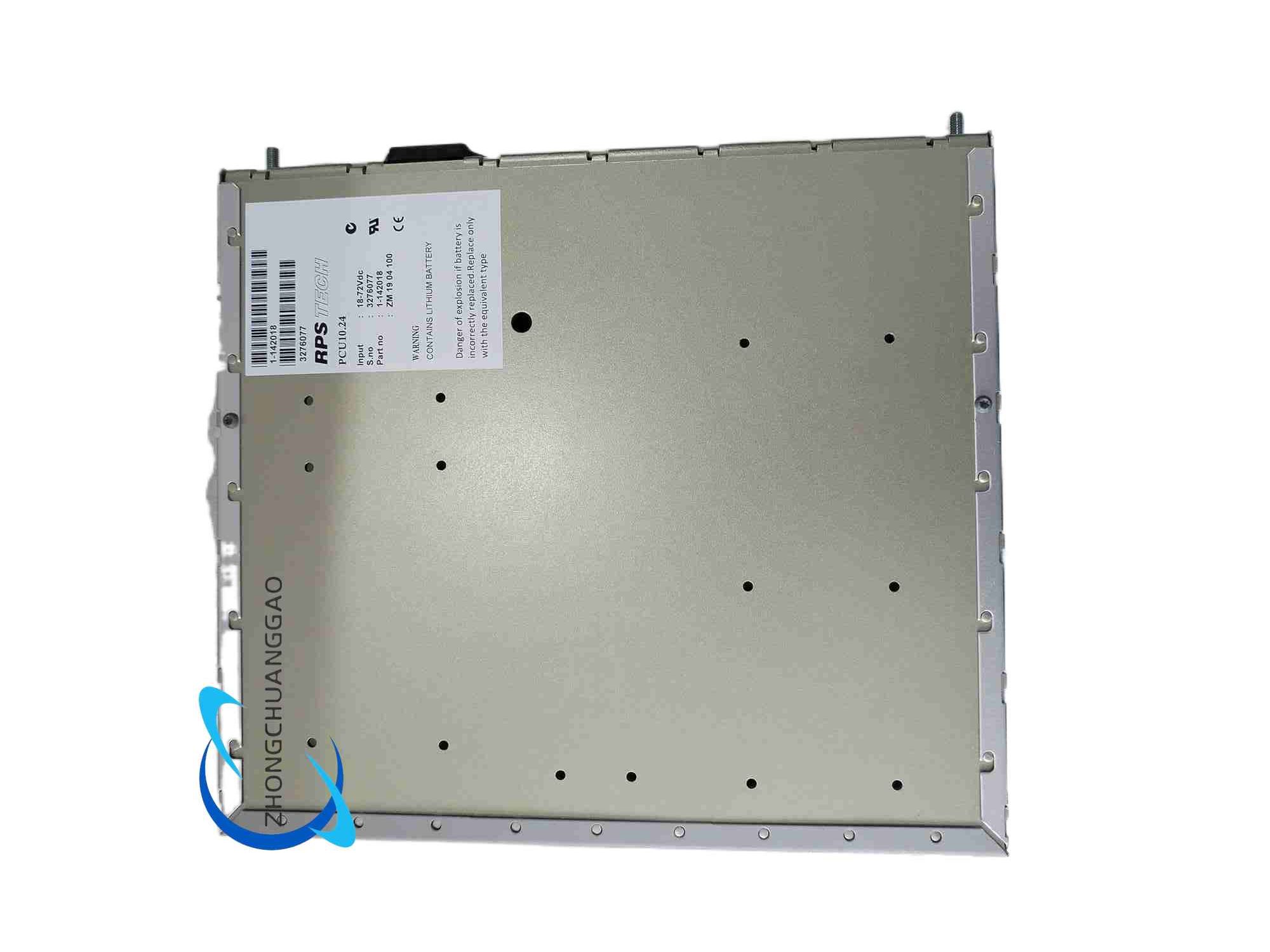
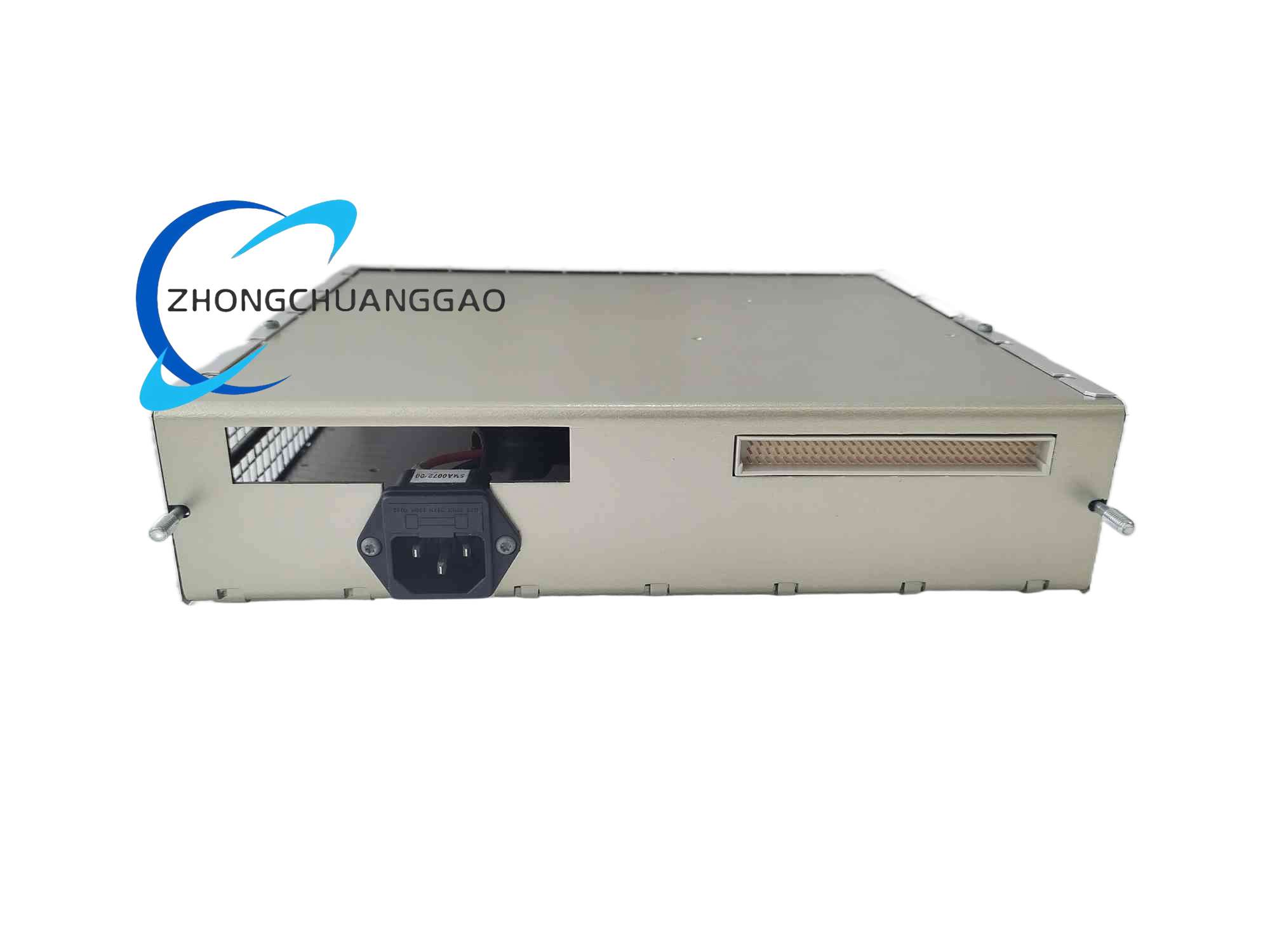
This DIN rail mounted power control unit is a core AC-DC conversion and power monitoring module developed by POWEC, designed for uninterruptible power supply management in industrial automation, communication base stations and power distribution systems. It integrates dual-channel stabilized DC output, real-time electrical parameter collection, fault diagnosis and Modbus communication linkage functions, supporting redundant power parallel operation to eliminate equipment downtime caused by single power failure.
Description
Core Technical Performance Parameters
- Input Electrical Specs
- Universal AC Input Range: AC 85V–264V, frequency 47Hz–63Hz
- Compatible DC Input Backup: DC 120V–370V
- Input Rated Power: 10W nominal power rating (model suffix 10.24 definition)
- Input Inrush Current: Max 12A peak transient current
- Output Electrical Specs
- Dual Isolated DC Output Channels: DC24V primary channel
- Output Voltage Regulation Accuracy: ±1% under full line and load fluctuation
- Output Ripple & Noise: ≤150mV peak-to-peak
- Power Conversion Efficiency: ≥90% at rated load
- Communication Specs
- Standard Interface: RS485 Modbus RTU, optional CANopen bus
- Data Scan Cycle: Minimum 20ms real-time parameter upload
- Environmental & Mechanical Specs
- Operating Temperature Range: -20°C ~ +70°C continuous operation
- Storage Temperature: -40°C ~ +85°C
- Protection Grade: IP20 cabinet internal rating
- Physical Dimension: 120mm(W) × 80mm(H) × 30mm(D)
- Net Weight: 0.45kg
Function & Feature Highlights
- Redundant Parallel Power Operation: Multiple PCU10.24 modules can be wired in parallel for hot backup, automatic load balancing without manual intervention
- Full-Range Multi-Layer Circuit Protection: Built-in hardware overvoltage, overcurrent, short-circuit, overtemperature lockout protection; automatic power cut-off when fault occurs, no secondary damage to downstream loads
- Remote Real-Time Monitoring & Control: Transmits output voltage, output current, internal temperature, fault alarm codes to upper SCADA/HMI system via Modbus; supports remote on/off control of output power
- Intelligent Fault Logging: Stores up to 500 historical fault records with timestamp for post-failure maintenance analysis
- Optimized Thermal Dissipation Structure: Integrated aluminum alloy heat sink inside enclosure, low heat accumulation under continuous full-load operation
- High EMI Suppression: Multi-stage LC filter circuit at input port, resists interference from frequency converters, induction furnaces and high-power motor equipment
Working Principle
The mains AC input first passes through the EMC filter circuit to eliminate grid harmonic and electromagnetic interference, then enters the high-frequency switching power conversion circuit to complete AC-DC rectification and voltage stabilization processing. The internal MCU real-time samples output voltage, current and module temperature signals, compares sampled values with preset threshold parameters. If parameter deviation exceeds safety range, the protection circuit immediately triggers output cutoff. The communication unit packages all real-time operating data and transmits to upper monitoring host through RS485 bus; meanwhile, the MCU accepts remote control commands to adjust output power state and load allocation when multiple modules run in parallel.
Material Composition & Structural Characteristics
- Enclosure Material: High-strength flame-retardant ABS plastic, UL94-V0 fire resistance rating, anti-corrosion and dust-proof
- Internal Circuit Board: Double-sided copper-clad FR4 PCB with 2oz thick copper for high current carrying capacity; all power components use industrial-grade solid capacitors and low ESR inductors
- Heat Dissipation Components: Extruded aluminum alloy heat sink attached to power MOSFET and transformer core
- Terminal Connectors: Screw-type copper alloy terminals with nickel plating for anti-oxidation, wire clamping range 0.5mm²–2.5mm²
- Mounting Structure: Standard 35mm DIN rail buckle integrated on enclosure back, quick slide-in fixed installation without additional fasteners
Installation Technical Requirements
- Mounting Carrier: Must install on standard NS35/7.5 DIN rail inside sealed electrical control cabinet, vertical mounting direction only, horizontal installation forbidden
- Ambient Installation Space: Minimum clearance 20mm above and below module for air convection heat dissipation; no heat-generating components (contactors, resistors) within 10cm surrounding area
- Wiring Standard: Input AC line uses 1.5mm² shielded cable, DC output line uses 2.5mm² copper wire; shield layer single-point grounding at cabinet ground bar
- Grounding Requirement: Module ground terminal connected to cabinet protective earth wire with resistance less than 0.5Ω
- Installation Environment Limit: Cannot install in outdoor open space, environment with water splash, corrosive gas or conductive metal dust accumulation
Typical Application Scenarios
- Industrial automation production line PLC, sensor and actuator stable DC power supply
- Communication base station cabinet 24V control circuit redundant power backup
- Wastewater treatment plant pump valve control system power monitoring unit
- Mining underground control cabinet low-voltage power conversion equipment
- Substation auxiliary control loop DC power monitoring and protection module
Operation & Maintenance Precautions
- Pre-power Inspection: Confirm all wiring terminals fully tightened before switching on input power; short-circuit test output port strictly prohibited without load equipment connected
- Load Matching Limit: Total connected load power cannot exceed rated 10W long-term continuous operation; short-time peak load allowed within 15W for maximum 30 seconds
- Maintenance Power Cut Rule: Must disconnect main AC input circuit breaker and wait minimum 5 minutes for internal capacitor complete discharge before opening enclosure for internal inspection
- Regular Maintenance Cycle: Clean dust accumulated on enclosure heat dissipation gaps every 3 months in dusty workshop environments; retighten all wiring terminals every 6 months to prevent loose contact heat generation
- Fault Handling Restriction: Do not disassemble internal circuit components without professional maintenance qualification; fault module must be replaced with original POWEC PCU10.24 module, mixed use of third-party non-matching power modules forbidden
- Temperature Monitoring Warning: If module surface temperature continuously exceeds 60°C under normal load, immediately reduce connected load power and check surrounding heat dissipation conditions
Reviews
There are no reviews yet.