
Product Short Description
Product Overview
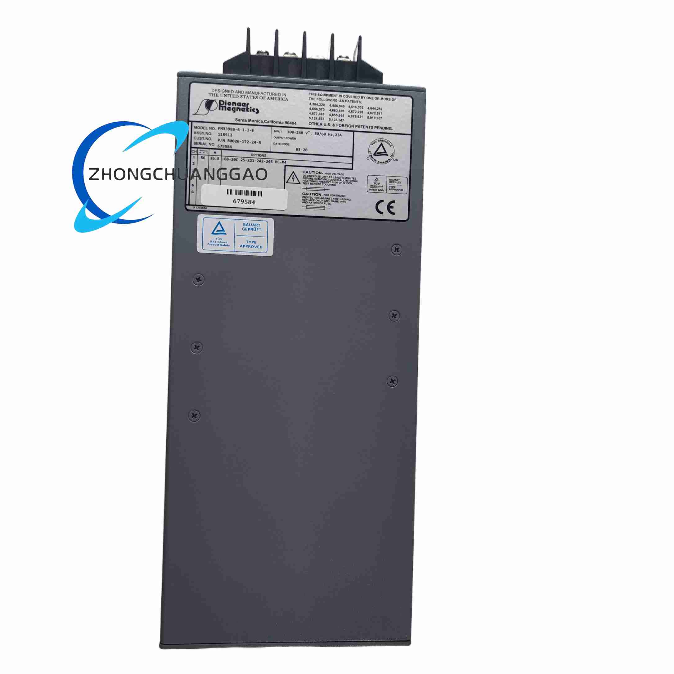
This product is a dedicated customized variant derived from the PM3398B universal high-power planar magnetic base platform, marked with unique suffix configuration code 6-1-3-E and internal engineering drawing reference number 80026-172-24 to lock fixed winding layout, electrical parameter indicators, insulation grade and mechanical terminal pin layout for specific industrial equipment customer project demand.
Description
Input Electrical Fixed Parameters
Input voltage range: 90 VAC ~ 264 VAC single-phase universal AC grid input
Input operating frequency: fixed 47 Hz ~ 63 Hz industrial grid frequency range
Built-in standard active power factor correction circuit, power factor ≥0.95 at full 6 A output load
Input reverse polarity and input overvoltage surge protection circuits integrated on input terminal block
Fixed output DC voltage: 24 VDC, output voltage tolerance ±1% under all load and input voltage fluctuation conditions
Continuous rated output current: 6 A, total rated output power 144 W
Transient peak output current: 9 A, sustainable for maximum 10 seconds for instantaneous equipment startup current demand
Line regulation: ±0.2% across full 90~264 VAC input voltage range
Load regulation: ±0.5% from 0 A no-load to 6 A full-load output current change
Output ripple & noise peak-to-peak value: less than 30 mV under full-load operating state
Primary winding to secondary winding isolation withstand voltage: 2500 VAC, continuous withstand 1 minute without breakdown, leakage current ≤1 mA
Internal winding insulation class: F-class high-temperature resistant insulation material, long-term continuous operating temperature up to 155°C
Insulation resistance between primary winding, secondary winding and module aluminum rack chassis ≥100 MΩ measured at 500 VDC test voltage
Standard unified PM3398B base platform rack dimension: 127 mm Width × 127 mm Depth × 292 mm Height
Mounting method: Standard industrial 5-inch rack horizontal locking installation, Elcon drawer-type hot-plug power connector fixed pinout layout defined by drawing 80026-172-24
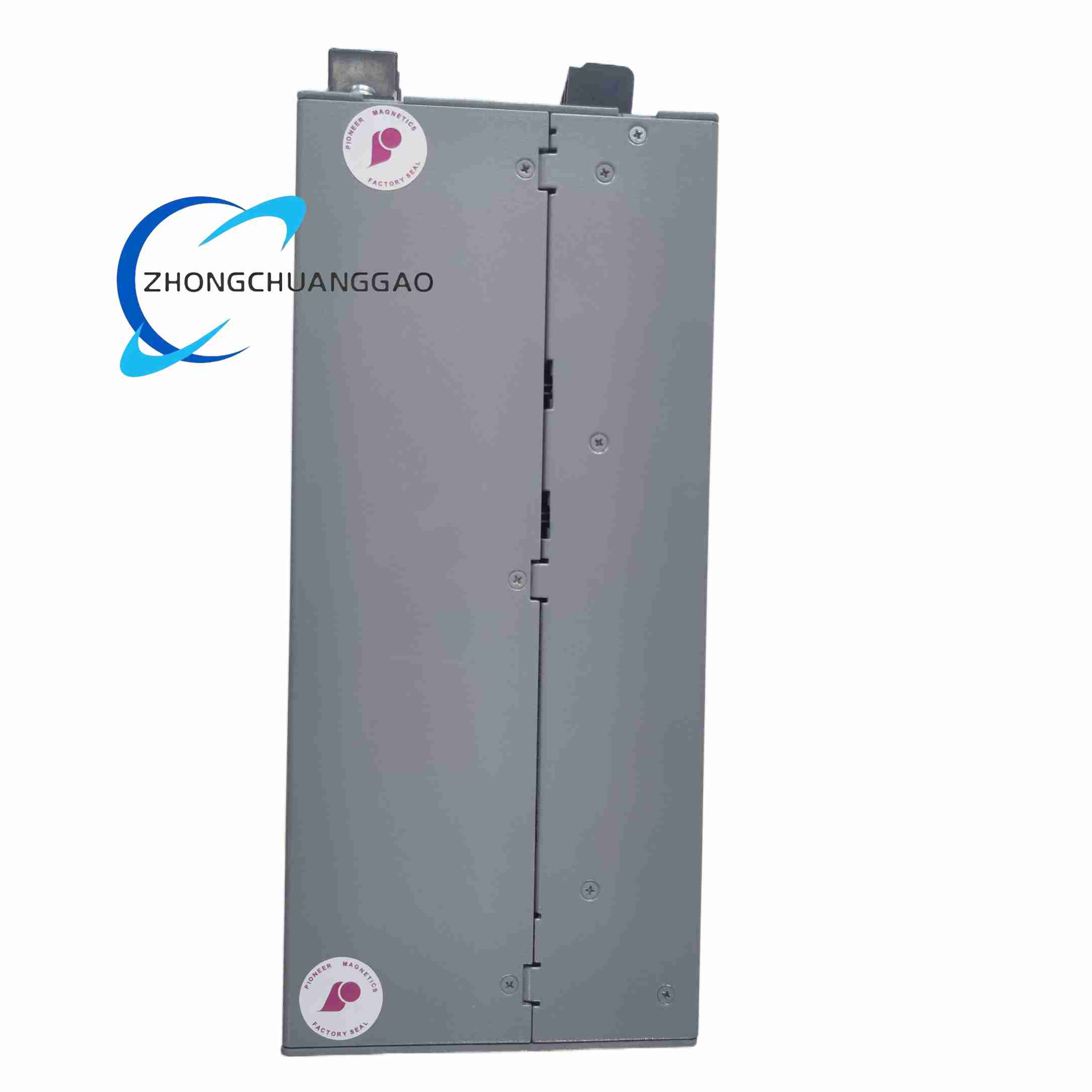
Housing material: Thickened extruded aluminum alloy rack shell, built-in automatic speed regulation forced air cooling fan assembly
Net weight of complete module: 5 kg
Continuous full-load operating temperature range: 0°C ~ +50°C, can deliver complete 144 W rated output power within this temperature interval
Storage temperature range (power disconnected, battery removed): -40°C ~ +85°C
Adaptable relative humidity range: 5% ~ 95% non-condensing air environment
Vibration and shock compliance: IEC 60068 industrial mechanical vibration test standard
EMC certification: IEC 61000-6-2 industrial electromagnetic immunity standard, UL safety certification, CE electromagnetic compatibility certification
Input overvoltage protection, input undervoltage lockout protection
Output overcurrent automatic current limiting protection
Output short-circuit continuous lockout protection with automatic reset after fault removal
Internal planar magnetic core and power switching tube over-temperature thermal power reduction shutdown protection
Output overvoltage clamping protection to prevent overvoltage breakdown of rear-end control board electronic components
- Planar Magnetic Core Custom Winding Structure
Primary winding fixed configuration: 6 turns single-strand high-temperature enameled copper wire (suffix code 6-1)
Secondary winding fixed configuration: 3 parallel laminated copper foil windings (suffix code 3), thick copper foil design improves high-current heat dissipation and reduces AC winding loss under 6 A full-load output operation
Enhanced encapsulation grade E: The entire magnetic core and winding assembly is fully sealed with high-temperature flame-retardant epoxy insulating resin with improved thermal conductivity, strengthening heat transfer between magnetic core and aluminum heat dissipation baseplate, suitable for continuous long-term full-load operation in medium-temperature industrial workshop environment
- Circuit Board Fixed Layout Design
PCB circuit board component layout strictly follows drawing 80026-172-24 fixed footprint, all high-current output circuit traces adopt widened thick copper layer layout to minimize circuit resistance and avoid abnormal heating under continuous 6 A output current
- Front Panel Connector Fixed Pin Definition
Elcon drawer-type hot-plug power connector pinout layout is uniquely defined by internal drawing 80026-172-24, pin assignment cannot be replaced with other PM3398B suffix variant connector pin layouts, mis-matched connector wiring will cause input-output short-circuit and permanent module burnout damage
The overall power conversion operating logic follows the universal PM3398B base platform multi-stage conversion flow, all electrical parameter thresholds, winding turns ratio and thermal encapsulation performance are fixed according to drawing 80026-172-24 customized specifications. The primary winding six-turn single-strand and secondary three-parallel copper foil winding layout realizes fixed 24 VDC 6 A output voltage transformation ratio, enhanced thermal encapsulation material accelerates internal heat conduction to aluminum rack shell forced air cooling system to control magnetic core operating temperature rise within safe range under continuous full-load operation. All fault protection trigger current, voltage and temperature threshold values are factory pre-calibrated and locked, field users cannot adjust protection threshold parameters through external configuration software or hardware potentiometers.
All mechanical rack mounting, electrical wiring, cabinet environmental layout and grounding installation rules follow the universal PM3398B base platform installation standard specifications, with one unique customized limitation: front panel Elcon power connector wiring must strictly follow drawing 80026-172-24 fixed pin assignment definition, cross-use of other PM3398B variant connector wiring pin layouts is prohibited, otherwise input power and output load circuit short-circuit faults will occur leading to module permanent hardware burnout damage.
Packaging machinery filling and labeling equipment centralized control cabinet power supply unit
Small-scale factory automation conveyor belt equipment low-voltage 24 VDC bus power module
Medium-capacity industrial AGV robot battery constant voltage charging power supply equipment
Water treatment small-scale environmental monitoring instrument centralized power supply rack
Machine tool auxiliary sensor and serial communication instrument isolated power conversion unit
All general operation, maintenance, troubleshooting and spare parts storage specifications follow the universal PM3398B base platform maintenance standard rules, with exclusive customized precautions:
- When replacing damaged modules on production equipment, only the complete model PM3398B-6-1-3-E with internal drawing code 80026-172-24 can be used as replacement spare parts; other PM3398B suffix variant models with different winding configuration codes and drawing numbers cannot be interchanged for equipment replacement use, mismatched variants will output incorrect voltage and burn rear-end control board electronic components.
- All equipment system PCB design, cabinet wiring schematic and spare parts procurement BOM documents must record the complete full part number including suffix codes and internal drawing reference number 80026-172-24, generic PM3398B base model number cannot replace the complete full part number for engineering design and procurement work.
Reviews
There are no reviews yet.