
Product Short Description
Product Introduction
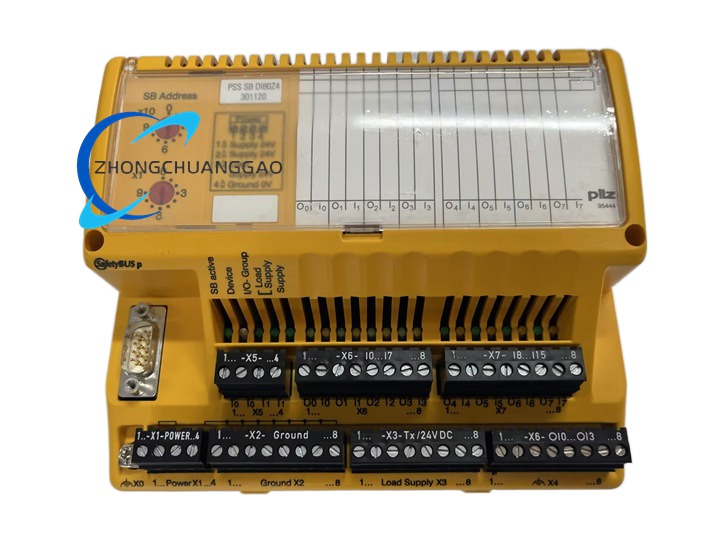
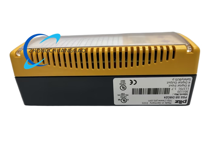
Manufactured by Pilz GmbH & Co. KG Germany, this module belongs to Pilz PSS SB distributed safety bus I/O system, dedicated to safety-related digital signal collection and output execution for machine safety control systems. It integrates 8 channels of safety digital input terminals and 4 channels of safety digital output terminals in a single compact module, communicates with PSS series safety CPU via internal safety bus backplane, collects signal state of field safety sensors (emergency stop buttons, safety door switches, light curtains) and outputs safety drive signals to safety actuators (safety contactors, solenoid interlock valves) to realize full safety logic control of automated machinery equipment.
Description
Core Technical Specifications
- Power Supply Electrical Parameters
- Module Operating Supply Voltage: 24 V DC (20.4 V ~ 26.4 V allowable fluctuation)
- Input Circuit Power Consumption: Max 1.8 W
- Output Circuit Rated Current per Channel: 0.5 A DC resistive load, short-circuit protected per channel
- Internal Isolation: Galvanic isolation between input channels, between input circuit and output circuit, isolation voltage 2000 V DC
- Digital I/O Channel Parameters
- Digital Input Channels: 8 channels, positive switching NPN input, input signal threshold 10 V DC high level, 5 V DC low level
- Digital Output Channels: 4 channels, positive switching safety transistor outputs, overload and short-circuit self-protection for each independent output channel
- Signal Response Time: Input signal filtering delay 3 ms, output signal execution response time ≤ 1 ms
- Physical & Mechanical Parameters
- Module Overall Dimensions (H × W × D): 140 mm × 170 mm × 65 mm
- Net Weight: 320 g
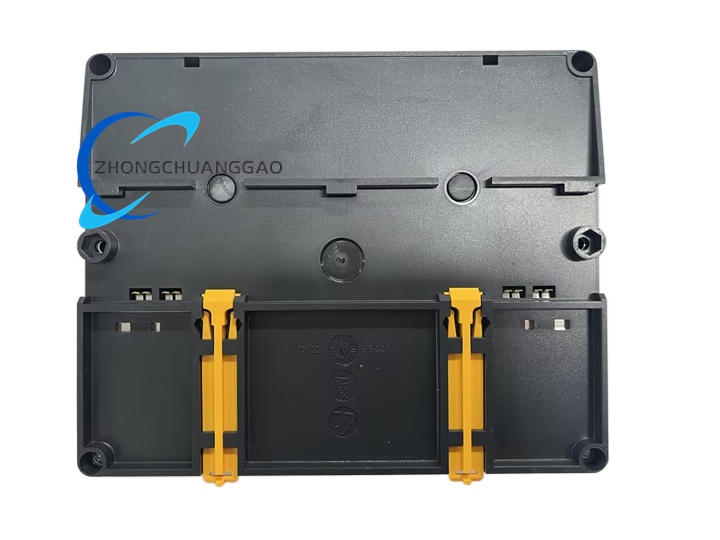
- Mounting Standard: Dual installation mode – standard 35 mm DIN top-hat rail mounting, or direct screw fixed mounting on metal installation plate via reserved mounting holes on module housing
- Environmental Operating Parameters
- Operating Temperature Range: 0 ℃ ~ +55 ℃
- Storage & Transport Temperature Range: -25 ℃ ~ +70 ℃
- Relative Humidity: 5% ~ 95% non-condensing
- Protection Grade: IP20 for terminal front face, IP30 module housing internal circuit protection
- Vibration Resistance: IEC 60068-2-6 standard, 10–150 Hz vibration continuous operation without signal misjudgment
- Functional Safety Certification Standards
- Safety Performance Level: PL e / Cat.4 per EN ISO 13849-1, SIL 3 per IEC 61508
- Machine Safety Standard Compliance: IEC 60204-1 machinery general safety standard
- EMC & Product Certification: CE, UL 508, RoHS industrial electronic component certification
Function & Feature Highlights
- Mixed 8DI + 4DO integrated design, single module completes both safety signal input collection and safety actuator output control, reducing total quantity of I/O modules installed in safety control cabinet, saving cabinet internal installation space and reducing bus wiring complexity.
- Independent LED status indicator for every single input and output channel on module front panel: green LED light on represents high-level active signal for input channels; green LED on means output channel switched on and load energized; rapid flashing LED indicates channel short-circuit, overload or open-circuit fault for fast on-site fault location without testing instrumentsManualsLib.
- Channel-level independent hardware protection circuit for all 4 output channels: each output transistor circuit integrates overcurrent, short-circuit and overheating protection; when short-circuit fault occurs on single output channel, only that single channel cuts off output automatically, all other input and output channels of the module keep normal operation without full module shutdown caused by single channel fault.
- Built-in hardware signal filtering circuit for all 8 digital input channels, filters out high-frequency electromagnetic interference pulse signals generated by on-site frequency converters, servo motors and welding equipment, eliminating false signal triggering and misjudgment of safety interlock logic caused by industrial electromagnetic noise.
- Safety bus hot-swappable support: module can be plugged and replaced on PSS SB safety bus rack backplane under continuous operation of the whole safety control system, no need to power off the entire safety rack, minimizing machine production downtime during maintenance and module replacement work.
- Complete internal module self-diagnostic logic: continuously monitors 24 V DC module supply voltage, backplane safety bus communication state, internal circuit chip temperature and each channel circuit health status; all detected fault codes are transmitted to upper-level Pilz safety CPU, fault information can be displayed on safety system operation screen and stored in fault history memory for maintenance traceability.
Material & Structural Composition
- Outer Housing Material: Flame-retardant high-impact ABS plastic, Pilz standard safety orange color (industry universal safety automation component color), UL94 V-0 fire retardant rating, resistant to machine tool cutting oil, coolant and weak acid cleaning liquid corrosion.
- Internal Circuit Board Material: High Tg FR4 multi-layer copper-clad printed circuit board, independent shielding ground copper layer between input signal circuit, output power circuit and safety bus communication circuit to eliminate circuit crosstalk and electromagnetic interference.
- Terminal Connection Components: Spring-cage screw terminal blocks with copper alloy conductive cores and nickel plating anti-oxidation surface treatment; each terminal block is separated by insulating partition to prevent adjacent terminal short circuit caused by loose wire strands.
- Heat Dissipation & Insulation Structure: Multiple vertical heat dissipation slits on module left and right side panels for natural convection heat dissipation; thick mica insulating sheets between high-current output transistor circuits and low-voltage input signal circuits to meet high voltage isolation safety requirements.
Working Principle
- Safety Digital Input Signal Collection Stage: 24 V DC active safety signals from field safety sensors (emergency stop buttons, safety door limit switches, safety light curtain signal outputs) are transmitted to the module’s 8 input channels; built-in hardware filter circuit eliminates electromagnetic noise interference pulses, valid high/low level signals are converted into digital binary data by internal signal processing chip, then packaged into safety bus protocol data frames.
- Safety Bus Data Transmission Stage: Packaged input signal digital data frames are transmitted through the PSS SB internal rack backplane safety bus to Pilz PSS series safety CPU; simultaneously, safety logic execution output commands issued by the safety CPU are received via the same safety bus, command data frames are parsed by the module’s internal communication processing chip.
- Safety Digital Output Actuation Stage: Parsed output switch-on/off commands control the 4 independent safety output transistor circuits; when switch-on command is received, corresponding output channel transistor conducts, 24 V DC drive power is supplied to connected safety actuators (safety contactor coils, safety interlock solenoid valves); when switch-off command is received, transistor cuts off output power supply to safety actuators to execute safety cut-off interlock protection action.
- Real-Time Fault Monitoring & Hardware Protection Stage: The module’s internal dedicated monitoring chip continuously scans all input channel signal integrity, output channel current load value, module supply voltage and internal circuit operating temperature; if abnormal parameters exceeding preset safety thresholds are detected (output short-circuit, input wire open circuit, undervoltage power supply), corresponding hardware protection circuit activates instantly to isolate the faulty channel, fault status data is uploaded to safety CPU for system-level fault alarm and record storage.
Application Scenarios
- Automated robotic welding workstations, automotive assembly production line safety control cabinets
- CNC machining centers, stamping presses, hydraulic forming machinery safety interlock control systems
- Automated packaging, palletizing, logistics conveyor equipment emergency stop & safety door protection systems
- Elevator maintenance safety interlock control, packaging machinery light curtain safety signal acquisition and output drive control
Installation Requirements
- DIN Rail Mounting Operation: Align the module’s top and bottom DIN rail buckles with standard 35 mm top-hat rail, push the module rearward firmly until both top and bottom buckles fully snap and lock onto the rail; shake the module lightly to confirm no sliding or loose fit on the rail.
- Alternative Screw Fixed Plate Mounting: Use M4 stainless steel machine screws to fix the module through four reserved mounting holes on module housing onto flat metal installation plate; ensure installation plate is reliably connected to cabinet protective earth bar via thick copper ground wire.
- Wiring Specification for Terminal Blocks: Allowable wire cross-section range: solid copper wire 0.5–2.5 mm², stranded wire with crimp copper ferrule 0.25–2.5 mm²; strip wire insulation to 7 mm length only, tighten terminal screws with standard screwdriver to torque value of 0.8 N·m to avoid loose wiring contact resistance overheating risk.
- Cabinet Environmental Installation Standards: Install the PSS SB safety bus rack in closed, air-conditioned electrical control cabinet; maintain minimum 20 mm vertical ventilation gap between adjacent modules on the rack, do not block module side heat dissipation slits with wiring harnesses or cable ties; install safety bus rack at least 50 cm away from high-power frequency converters, servo drive power modules and welding power sources to reduce strong electromagnetic interference impact.
- Protective Grounding Requirement: Connect the metal DIN rail or metal mounting plate of the safety rack to the control cabinet’s dedicated protective earth bar with copper ground wire cross-section ≥ 4 mm², single-point reliable grounding to eliminate electrostatic accumulation and leakage electric shock hazard.
Usage & Maintenance Precautions
- Electrostatic Discharge Protection Operation: Must wear anti-static wristband firmly connected to cabinet protective earth bar before touching, disassembling or replacing the module; static electricity generated by human body will permanently damage internal sensitive signal processing chips and safety bus communication chips.
- Pre-Power-On Wiring Inspection Standard: After completing all input/output and backplane bus wiring, perform two rounds of inspection: first visual inspection to confirm no exposed copper wire strands bridging adjacent terminals; second light pull each connected wire to verify terminal screw clamping firmness without loose wire sliding.
- Regular Preventive Maintenance Cycle: Every 6 months perform visual inspection of module housing for cracks, terminal blocks for burn marks caused by overheating loose wiring, front panel LED indicators for damage; use dry anti-static soft brush to clean dust accumulated on heat dissipation slits and terminal surface, strictly prohibit use of water-based liquid cleaning agents or compressed air high-pressure blowing to avoid moisture or dust entering internal circuit components.
- Strict Load Limitation for Output Channels: Never connect load current exceeding rated 0.5 A DC per single safety output channel; when driving high-power safety contactor coils or large solenoid valves with inductive load characteristics, install external parallel surge absorption diodes across the actuator coil terminals to absorb reverse electromotive force voltage spikes and prevent output transistor breakdown damage.
- Prohibited Operating Environments & Operations: Do not install the module in open outdoor control cabinets, or environments with continuous oil mist, corrosive acid/alkali gas, conductive metal dust or excessive humidity (condensation on module surface); do not input supply voltage lower than 20.4 V DC or higher than 26.4 V DC to module power terminals; disassembly of module outer housing without professional Pilz authorized maintenance personnel is forbidden, disassembly will destroy internal safety isolation and bus communication circuit structure, rendering the module unable to meet SIL 3 functional safety certification standards.
- Spare Module Storage Requirements: Store unused spare modules in sealed anti-static packaging bags, placed in constant temperature (15–25 ℃) dry storage cabinet; avoid long-term storage in high humidity, chemical corrosion or direct sunlight environment to prevent circuit board oxidation and plastic housing aging brittleness.
Reviews
There are no reviews yet.