
Product Short Description
Product Introduction
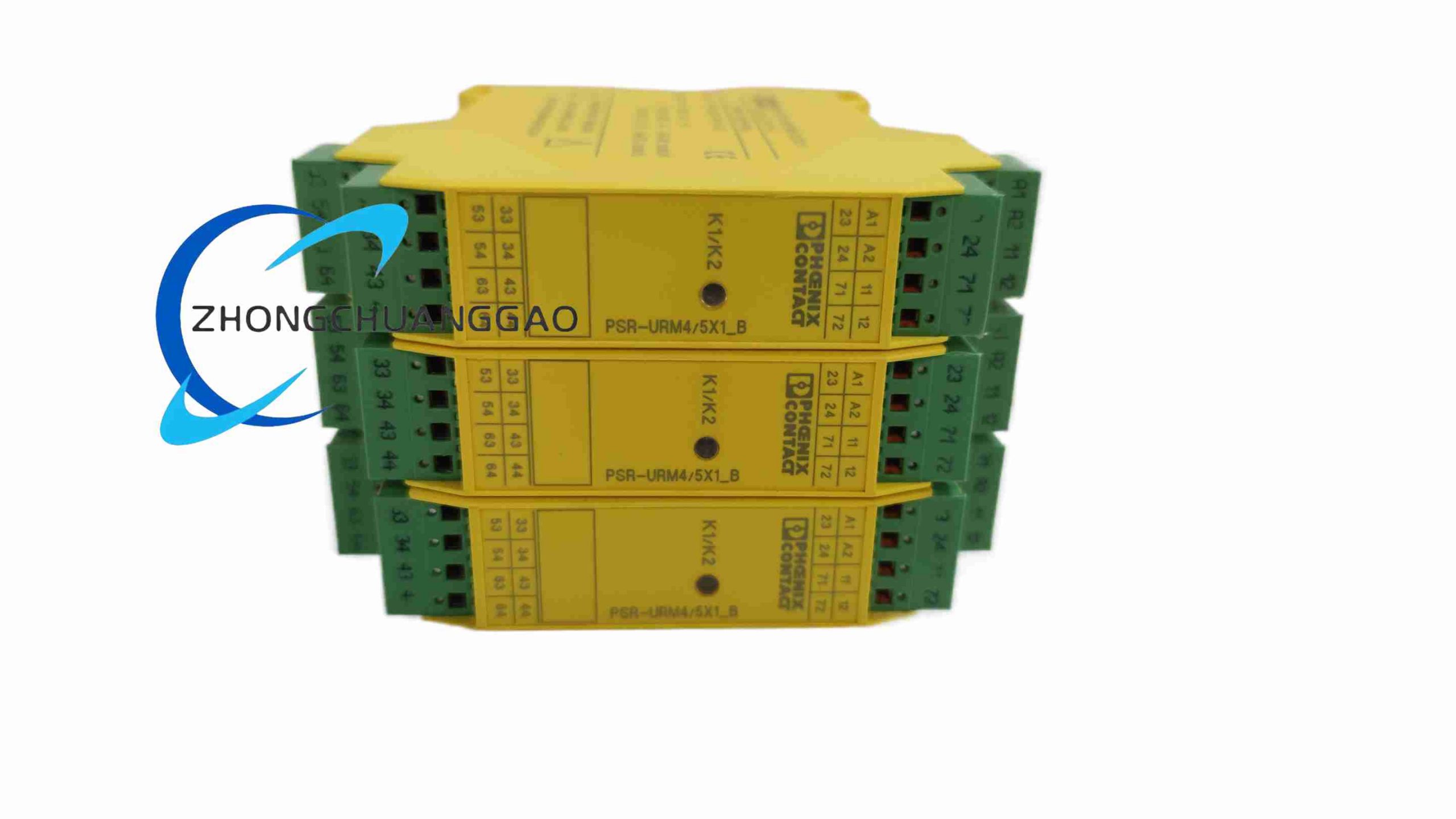
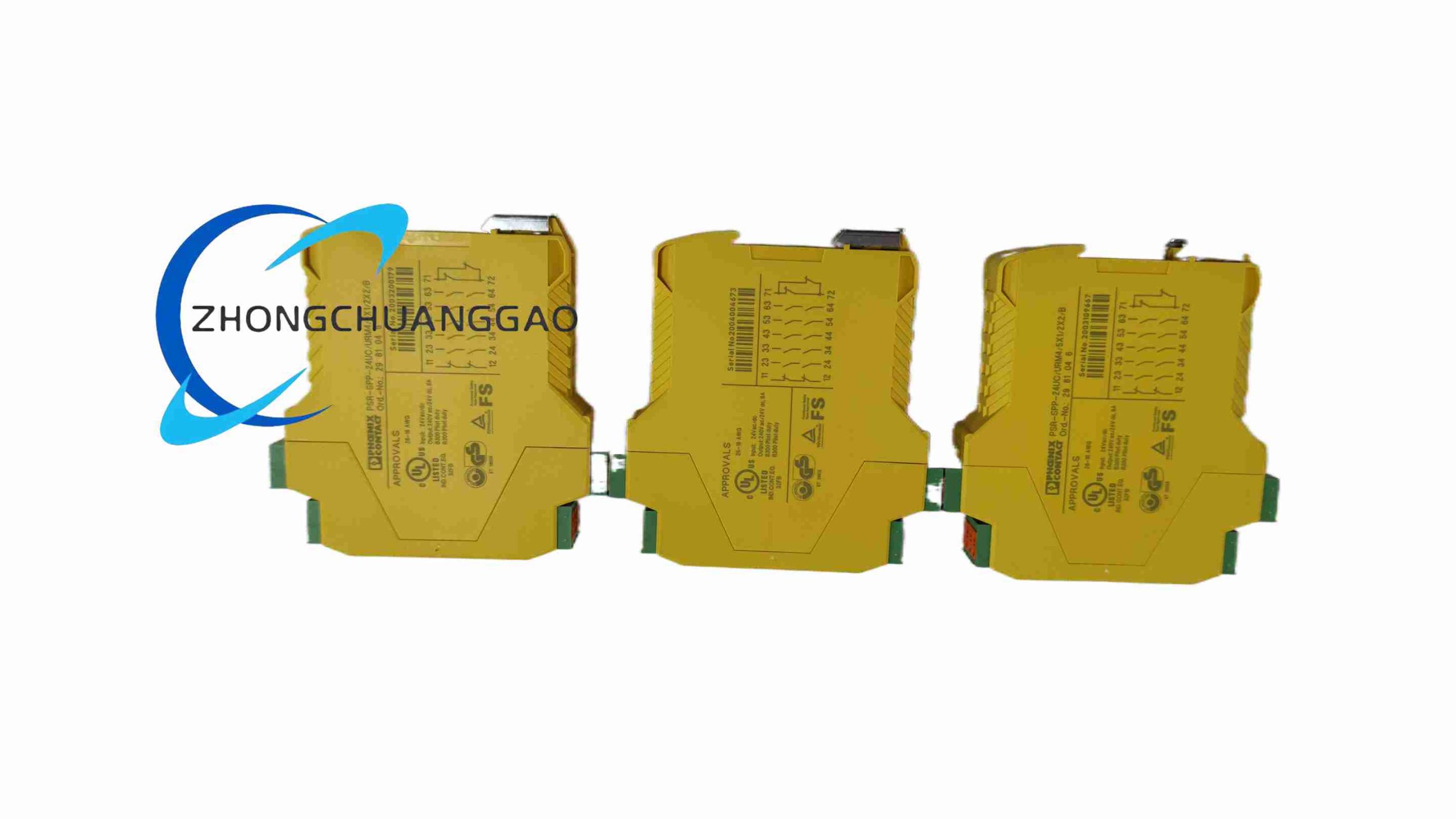
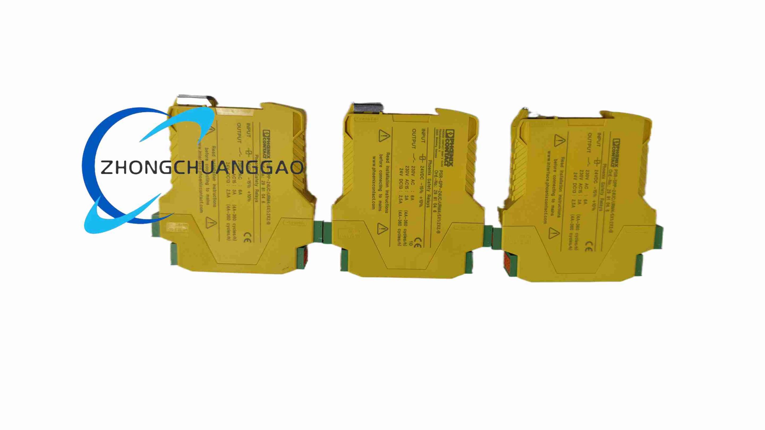
This product belongs to Phoenix Contact PSRclassic safety relay series, designated as safety contact expansion auxiliary module matched with main safety relay unit. It adopts force-guided contact electromechanical relay structure fully complying with IEC/EN 61810-3 safety standard, used to expand the quantity of safety switching contacts of main safety relays in machinery safety control circuits, realizing multi-group synchronous safety cut-off control for safety doors, two-hand operation switches, emergency stop buttons and light curtains on automated production equipmentPhoenix Co…
Description
Core Technical Specifications
- Control Circuit Power Parameters
- Rated Control Supply Voltage: 24 V UC (24 V AC / 24 V DC universal input)
- Allowable Voltage Fluctuation Range: 20.4 V ~ 26.4 V
- Control Circuit Power Consumption: Max 2.2 VA
- Safety Contact Output Parameters
- Safety Contact Configuration: 5 Normally Open (N/O) safety contacts, 1 Normally Closed (N/C) monitoring contact, 1 confirmation current feedback path
- Rated Switching Current per N/O Contact: 6 A resistive load
- Maximum Breaking Capacity (AC 250 V resistive): 1500 VA
- Minimum Switching Load: 10 mA / 10 V AC/DC
- Mechanical Service Life: 10,000,000 switching cycles
- Electrical Service Life (6 A resistive load): 100,000 cycles
- Physical & Mechanical Parameters
- Module Overall Dimensions: 22.5 mm (W) × 114.5 mm (H) × 112 mm (D)
- Net Weight: 185 g
- Mounting Standard: 35 mm standard DIN top-hat rail mounting
- Terminal Connection Type: Push-in spring pluggable terminal block, tool-free wiring
- Environmental Operating Parameters
- Operating Temperature Range: -20 ℃ ~ +55 ℃
- Storage Temperature Range: -40 ℃ ~ +70 ℃
- Relative Humidity: 10% ~ 90% non-condensing
- Protection Grade: IP20 for front terminal area, IP40 for module housing
- Shock & Vibration Standard: IEC 60068-2-6 compliant for industrial machine vibration
- Safety & EMC Certification Standards
- Functional Safety Grade: Cat.4, PL e per EN ISO 13849-1, SIL 3 per IEC 61508
- Product Safety Standard: IEC 60947-5-1, IEC 60947-5-5, ISO 13850 emergency stop standard
- EMC Certification: CE industrial EMC Class A, noise suppression built-in free of external filter
Function & Feature Highlights
- Force-guided safety contact structure: All internal relay contacts are mechanically interlocked, N/O and N/C contacts cannot be closed simultaneously under any mechanical failure condition, completely eliminating the risk of dangerous short circuit in safety interlock circuits.
- Universal 24 V AC/DC control power input, compatible with all mainstream industrial machine control cabinet power supply systems, no need to replace modules for different AC/DC control power environments.
- Tool-free Push-in pluggable terminal design: stranded wires with ferrules or solid copper wires can be directly inserted into terminals without screwdriver; terminal block can be entirely pulled out for quick wiring replacement without disassembling the whole module from DIN rail.
- Independent green LED power status indicator on front panel: LED light on indicates normal control power supply; LED off means control circuit power loss, convenient on-site visual fault judgment without measuring instruments.
- Modular cascading expansion function: Multiple identical expansion modules can be directly cascaded side-by-side on DIN rail with no additional wiring jumpers, each expansion module adds 5 groups of independent safety switching contacts for multi-channel equipment safety cut-off control.
- Built-in inductive load suppression diode in each relay coil circuit: automatically absorb reverse electromotive force generated by inductive loads such as contactors and solenoid valves, protecting internal relay coils from breakdown damage caused by voltage spikes.
Material & Structural Composition
- Module Housing Material: Flame-retardant polyamide PA66 plastic, RAL 1018 safety yellow color (industry standard safety component color), UL94 V-0 fire resistance rating, oil and coolant corrosion resistant for machine tool workshop environment.
- Relay Contact Material: AgSnO₂ silver tin oxide alloy for safety switching contacts, anti-welding, anti-oxidation and arc ablation resistance, maintaining stable contact resistance after millions of switching cyclesPhoenix Co….
- Terminal Conductive Parts: High-purity copper alloy with 0.2–0.4μm gold plating on contact surfaces, low contact resistance and long-term anti-oxidation performance; spring pieces made of high-elastic beryllium copper to ensure stable wire clamping force.
- Internal Insulation Structure: Multi-layer mica insulation sheets between relay coil and contact circuits, air clearance and creepage distance fully meet high-voltage isolation safety standards between control circuit and power switching circuit.
Working Principle
- Control Signal Input Stage: 24 V AC/DC control power signal transmitted from main safety relay coil auxiliary circuit is input to the internal relay coil of this expansion module, generating electromagnetic suction force after coil energization.
- Safety Contact Actuation Stage: Electromagnetic suction pulls the force-guided contact movable armature, all 5 N/O safety contacts close synchronously, single N/C monitoring contact opens simultaneously; when control power is cut off, coil electromagnetic force disappears, built-in return spring resets all contacts to original state, all N/O contacts open to cut off safety control circuits.
- Safety Monitoring Feedback Stage: The independent N/C monitoring contact transmits contact state feedback signal back to main safety relay control circuit; main relay continuously monitors whether expansion module contacts act synchronously, once contact asynchronous action fault is detected, main relay immediately triggers full safety circuit power cut-off interlock protection.
- Surge Suppression Protection Stage: When relay coil power supply is disconnected, reverse inductive voltage spike generated by coil is absorbed by built-in parallel suppression diode, avoiding high voltage breakdown of coil insulation and interference to surrounding low-voltage control signal circuits.
Application Scenarios
- Automated stamping, injection molding, CNC machine tool safety interlock control cabinets
- Automated assembly production lines, packaging machinery, robotic workstation emergency stop & safety door control circuits
- Elevator maintenance safety interlock, warehouse automatic conveyor equipment safety cut-off systems
- Pharmaceutical, food processing machinery light curtain safety protection multi-channel switching control
Installation Requirements
- DIN Rail Mounting: Snap the module bottom buckle onto standard 35 mm DIN top-hat rail, push downward until the bottom locking buckle clicks to fully lock; ensure the module cannot slide left and right on the rail under vibration.
- Wiring Specification: Allowable wire cross-section range for Push-in terminals: solid wire 0.5–1.5 mm², stranded wire with crimp ferrule 0.25–1.5 mm²; wire stripping length strictly controlled at 8 mm to prevent exposed copper wire short circuit between adjacent terminalsPhoenix Co….
- Cabinet Environmental Installation Condition: Install safety relay modules in closed electrical control cabinets, maintain at least 10 mm horizontal gap between adjacent modules for heat dissipation; avoid installing near high-power frequency converters or welding equipment to reduce electromagnetic interference.
- Grounding Requirement: Connect the control cabinet metal DIN rail to cabinet protective earth bar with 4 mm² copper ground wire, ensure reliable equipment protective grounding for leakage safety protection.
Usage & Maintenance Precautions
- Wiring Inspection Before Power-On: After completing all terminal wiring, pull each wire slightly to verify firm clamping; visually check no exposed copper strands bridging two adjacent terminals to prevent short circuit fault.
- Load Matching Restriction: Do not connect load current exceeding 6 A per single N/O safety contact; when controlling multiple inductive loads (solenoid valves, contactors), install additional external surge absorption components for high-power inductive loads exceeding 3 A.
- Regular Maintenance Cycle: Every 12 months, visually inspect module housing for cracks, terminal block for burn marks caused by loose wiring; clean dust accumulated on front LED indicator and terminal surface with dry soft brush, do not use liquid cleaning agents.
- Prohibited Operating Conditions: Do not install the module in environments with continuous oil mist, strong corrosive acid/alkali gas or conductive metal dust; do not input control supply voltage higher than 26.4 V AC/DC, overvoltage will burn internal relay coils permanently.
- Fault Replacement Standard: If safety contacts show welding failure or asynchronous action fault detected by main relay, replace the entire expansion module directly; disassembly and repair of internal relay components are not allowed, disassembly will destroy force-guided contact safety interlock mechanical structure.
Reviews
There are no reviews yet.