
Product Short Description
Product Introduction
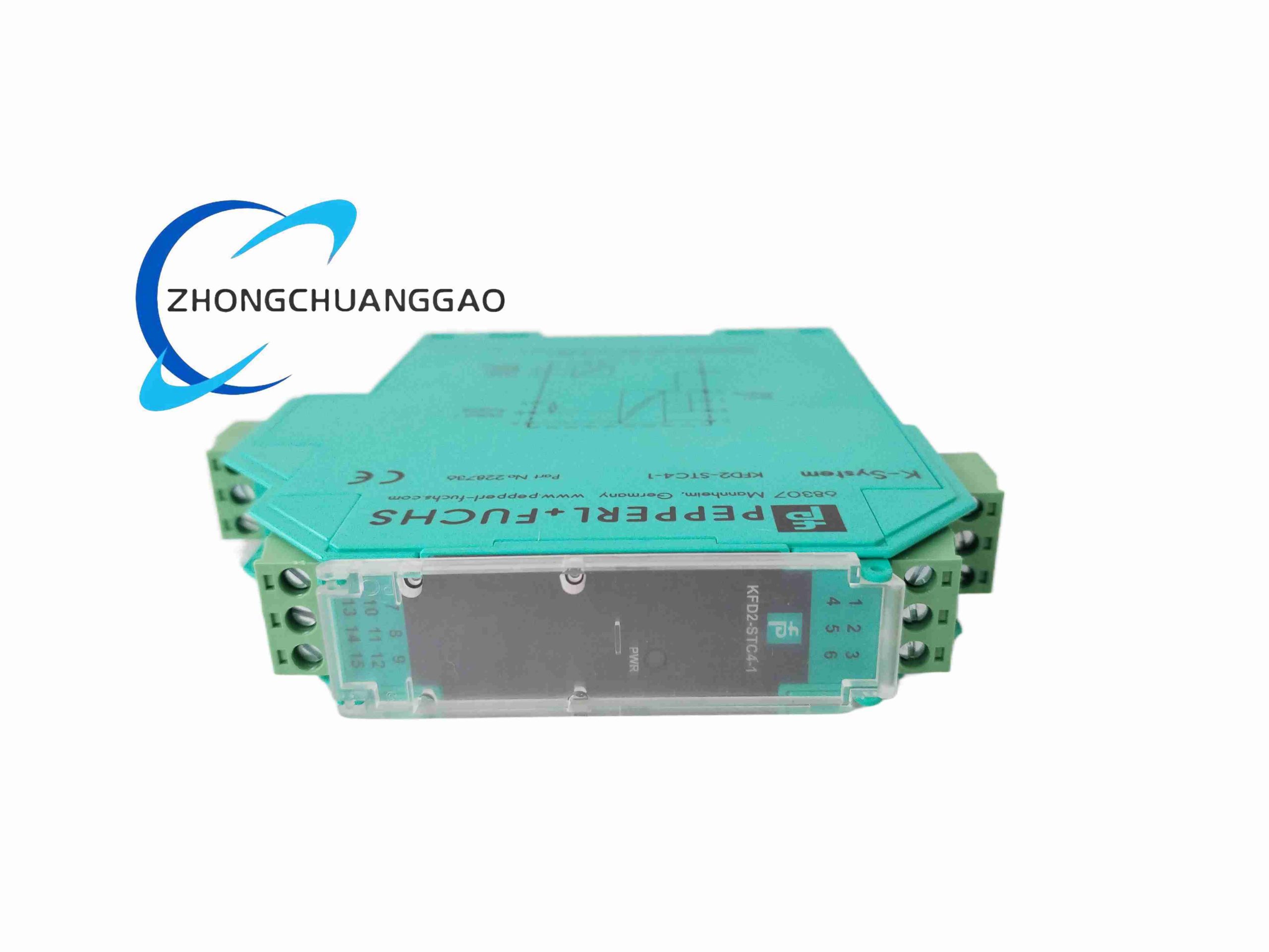
4-channel galvanic isolated loop power supply for standard 2-wire SMART analog transmitters deployed in non-explosive industrial zones. Provides field sensor loop power, linear analog signal isolation and bidirectional HART digital signal transparent transmission between field transmitters and DCS/PLC control input cards.
Description
Technical & Electrical Specifications
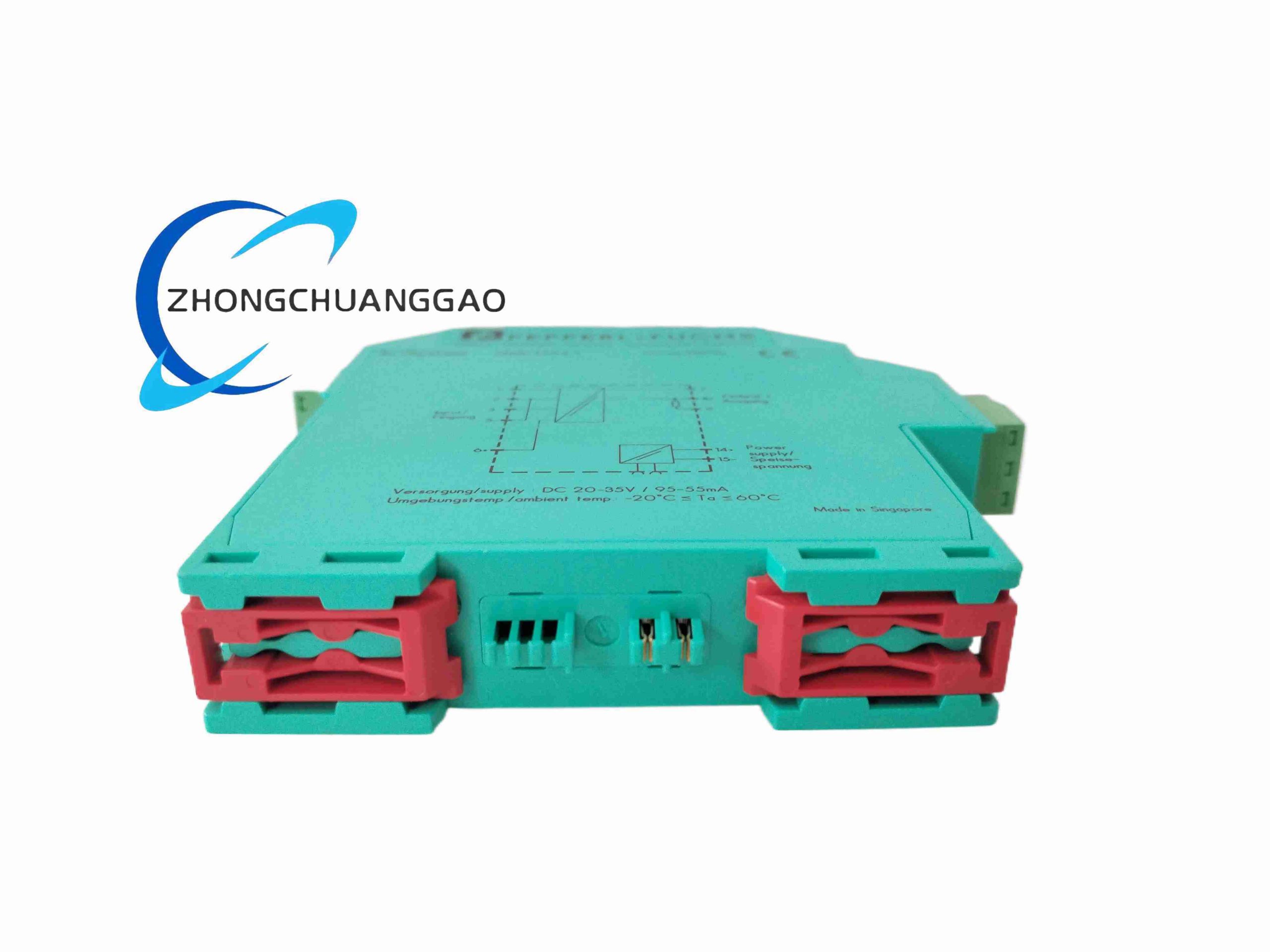
- Rated Supply Voltage: 20 V DC ~ 35 V DC
- Total Module Power Consumption: 1.8 W
- Max Power Dissipation: 1.4 W
- Per-Channel Field Input Terminals: 1+,2-,3 / 5-,6+
- Field Input Signal Range: 0 mA ~ 20 mA / 4 mA ~ 20 mA
- Minimum Available Field Loop Voltage @ 20 mA: ≥ 16 V DC
- Max Voltage Drop Across Input Terminals @ 20 mA: ≤ 2.4 V DC
- Control Side Output Terminals: 7-,8+,9 per channel
- Output Signal Range: 4 mA ~ 20 mA; overload cutoff > 25 mA
- Max Permissible Output Load Resistance: 800 Ω at 20 mA
- Output Signal Ripple Noise: ≤ 50 µA eff
- Total Measurement Deviation @ 20 °C Full Scale: ≤ 10 µA
- Temperature Drift Coefficient: ≤ 20 ppm/K
- Input/Output Bandwidth (-3 dB): 0 Hz ~ 7.5 kHz
- Signal Settling Time: 200 µs
- Isolation Standard: Basic insulation EN 50178
- Rated Insulation Voltage: 253 V eff
- Functional Safety Rating: SIL 2 IEC 61508
- Fault Detection Threshold: Signal outside 3 mA ~ 22 mA triggers dedicated fault relay output
Mechanical & Material Specifications
- Overall Dimension (W × H × D): 20 mm × 124 mm × 115 mm
- Housing Material: Flame-retardant green polycarbonate V0 grade
- Protection Class: IP20 cabinet-only installation
- Mounting Standard: 35 mm EN 60715 DIN rail
- Connection Terminals: Screw clamp wire terminals
- Net Weight: Approx. 200 g
Environmental Parameters
- Operating Ambient Temperature: -20 °C ~ +60 °C
- Storage Temperature Range: -30 °C ~ +70 °C
- Pollution Degree Class 2, Overvoltage Category II
Function Features
- Four independent fully isolated analog channels for multi-transmitter parallel signal conditioning
- Bidirectional transparent HART digital communication pass-through for SMART transmitter remote calibration
- DIP switch configurable output mode: current source, current sink, voltage source
- Global common disable input to lock all four channel outputs simultaneously
- Per-channel line fault detection for open circuit / short circuit field wiring faults
- SIL 2 certified for non-hazardous safety instrumented analog control loops
- Wide 20–35 V DC universal industrial power supply input range
Working Principle
Onboard DC-DC isolated power converter generates stabilized loop power for each connected 2-wire field transmitter. Analog current signal from field side passes through linear optocoupler isolation barrier to eliminate ground loop interference. HART high-frequency digital modulation signals superimposed on analog current are fully coupled across isolation without attenuation. Output driver circuit reconstructs standardized 4–20 mA signal for control system input acquisition. Out-of-range signal sampling triggers discrete fault output relay activation.
Advantage Highlights
- Four-channel compact design reduces DIN rail cabinet space versus single-channel isolators
- Full HART transparency eliminates need for separate HART multiplexer hardware
- Built-in common global disable input simplifies emergency process shutdown logic
- Ultra-fast 200 µs settling time supports high-speed closed-loop process control
- Low temperature drift ensures consistent measurement accuracy across full operating temperature band
- SIL 2 certification allows deployment in non-hazardous safety critical control systems
Applicable Industries
Water & wastewater treatment, food & beverage processing, power generation thermal plants, HVAC industrial systems, pulp & paper manufacturing, general factory process automation
Installation Requirements
- Install exclusively inside IP40+ sealed electrical control cabinets
- Mount horizontally on standard 35 mm top-hat DIN rail; vertical mounting prohibited
- Separate field sensor wiring and control system wiring via internal cabinet cable dividers
- Supply power must be stabilized SELV 24 V DC industrial power supply unit
- Maintain minimum 8 mm horizontal gap between adjacent heat-generating power modules
Usage Precautions
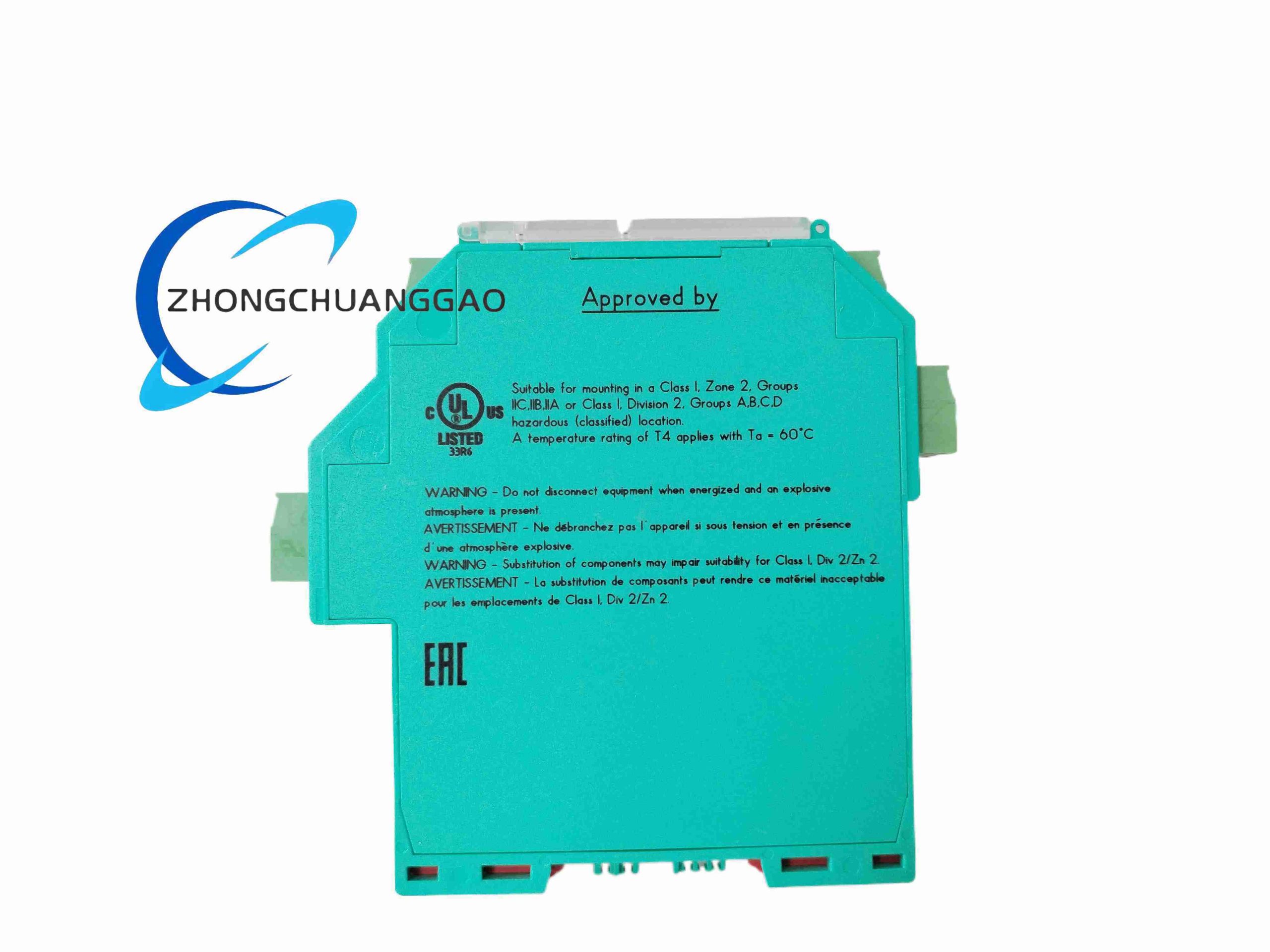
- Do not connect module to field wiring located within classified hazardous gas/dust zones
- Total output load resistance must not exceed 800 Ω per individual channel
- For SIL safety loop deployment, perform annual full function calibration verification
- Avoid installation adjacent to high-frequency variable frequency drive (VFD) power modules without EMC shielding
- Disconnect power supply before modifying DIP switch configuration settings
- Do not daisy-chain multiple KFD2-STC4-1 modules on single unregulated power rail
Reviews
There are no reviews yet.