
Product Short Description
Product Overview
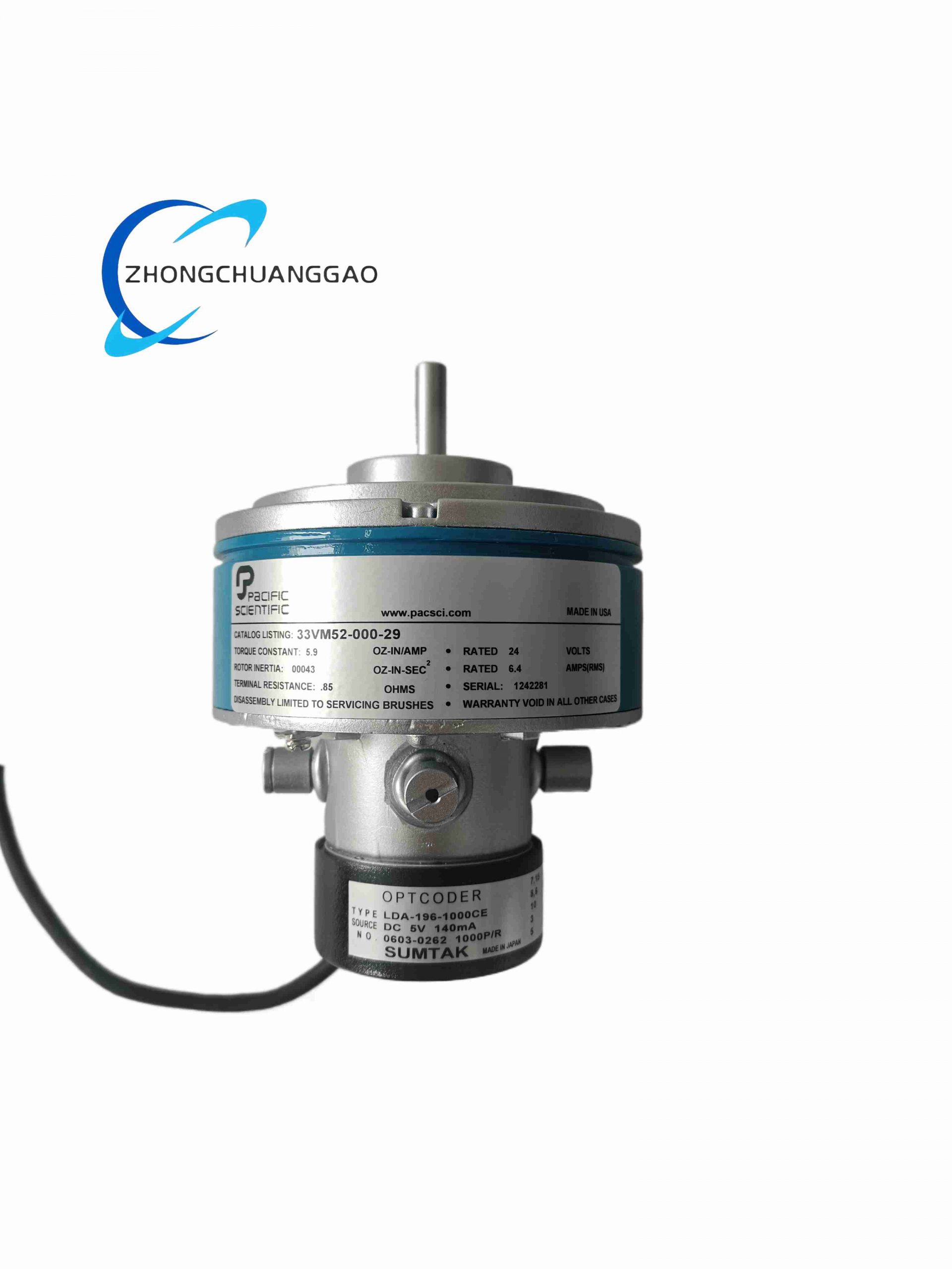
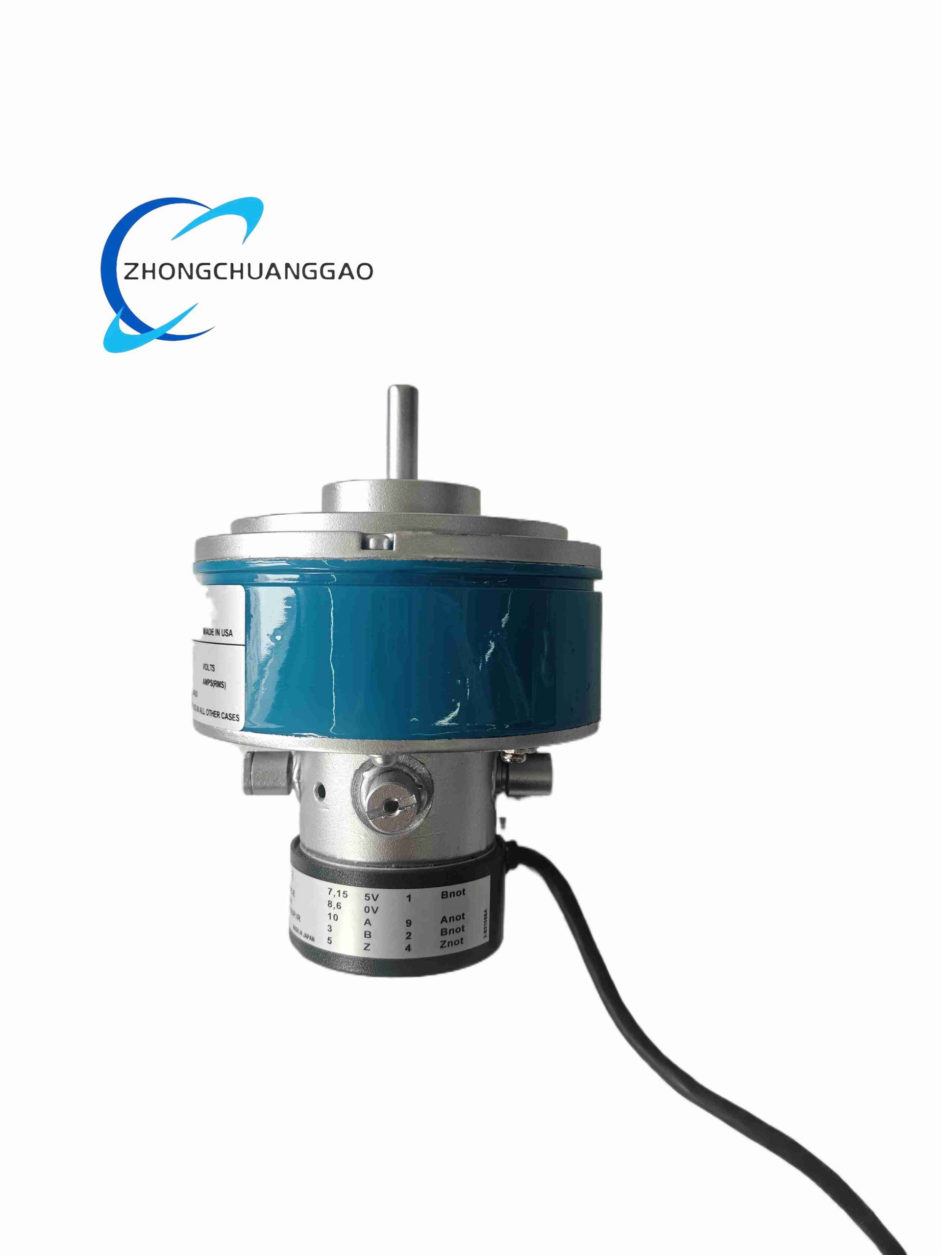
The 33VM52-000-29 is a high-torque NEMA 34 frame hybrid stepper motor manufactured by Pacific Scientific, paired with a factory-mounted LDA-196-1000CE 1000-line incremental closed-loop encoder for servo-grade closed-loop stepper control. This assembly eliminates open-loop step loss common to standard stepper motors, combining low-cost stepper architecture with high-precision encoder feedback for mid-range positioning automation. The model suffix -000-29 defines custom winding resistance and shaft dimension specifications for OEM industrial equipment matching.
Description
Core Technical Specifications (Motor + Encoder Combined)
Motor Parameters
- Frame Standard: NEMA 34 (86 mm square flange)
- Step Angle: 1.8° full step (200 steps per full rotation)
- Phase Configuration: Two-phase bipolar winding
- Rated Phase Current: 6.2 A RMS per phase
- Holding Torque: 12.8 N·m stationary holding torque
- Rotor Inertia: 0.0014 kg·m² low inertia rotor design
- Winding Resistance: 0.41 Ω per phase; Winding Inductance: 4.8 mH per phase
- Operating Temperature: -20 °C to +70 °C surface housing temperature
- Insulation Class: Class B (130 °C maximum winding temperature)
LDA-196-1000CE Encoder Parameters
- Encoder Type: Optical incremental quadrature encoder
- Line Count Resolution: 1000 lines per rotation
- Output Signals: A, /A, B, /B, Z, /Z differential line driver (RS422 standard)
- Power Supply for Encoder: 5 V DC ±5%, 120 mA max current draw
- Shaft Bore Diameter: Matching motor shaft diameter 14 mm press-fit mounting
- Encoder Housing Protection: IP50 dust-resistant rating
Functional Features
- Closed-Loop Step Loss Elimination: LDA-196-1000CE encoder feeds real-time shaft position to compatible Pacific Scientific stepper drives to detect missed steps and automatically compensate positioning error
- High Static Holding Torque: Optimized hybrid rotor magnetic circuit maintains rigid load positioning without continuous drive current hold mode
- Low Vibration Winding Design: Skewed stator tooth structure reduces cogging torque and mechanical resonance at mid-range operating speeds
- Differential Encoder Signal Output: RS422 differential wiring resists industrial electromagnetic interference for long-distance signal transmission up to 50 meters
- Dual Connection Wiring Terminals: Separate terminal blocks for motor power windings and encoder signal cables to isolate high-current and low-signal circuits
- Zero Index Pulse Alignment: Encoder Z-index pulse precisely aligned with motor electrical zero position for consistent equipment homing across multiple units
Material Composition
- Motor Stator Housing: Die-cast aluminum alloy black powder coated
- Rotor Core & Stator Lamination: Cold-rolled silicon steel laminated sheets with high permeability coating
- Rotor Permanent Magnet: Samarium-cobalt rare earth magnet for stable performance at elevated operating temperatures
- Motor Output Shaft: Alloy steel induction hardened, DIN standard flat keyway
- Encoder Housing: Glass-filled PBT engineering plastic with aluminum rear mounting flange
- Encoder Internal Optical Components: Infrared LED light source, silicon photodiode sensor array, glass code disk with precision etched grating lines
Structural Characteristics
- NEMA 34 standard 86 mm square front mounting flange with four 1/4-20 UNC threaded mounting holes
- Stacked coaxial structure sequence: Encoder rear housing → encoder code disk assembly → stepper motor rear end cap → stator winding core → rotor assembly → front output shaft bearing housing
- Double shielded ball bearing set at motor front and rear ends to support high radial and axial load capacity
- Separate cable exit ports: Side port for motor power cable, rear port for encoder signal cable
- Encoder unit factory pre-aligned and press-fitted to motor rear shaft to eliminate installation alignment deviation
- Axial through-hole design in encoder rear cover for manual shaft rotation access during machine commissioning
Working Principle
Stepper Motor Operating Principle
- Two-phase bipolar drive pulses energize stator windings in sequential phase patterns to generate rotating electromagnetic magnetic fields
- Rotor permanent magnet poles align sequentially with stator energized poles, producing discrete 1.8° rotational steps per full pulse cycle
- Drive microstep subdivision (up to 256 microsteps per full step) interpolates intermediate positions for smooth low-speed rotation
LDA-196-1000CE Encoder Feedback Principle
- 5 V DC supply energizes encoder internal infrared LED light source, projecting light through precision glass grating code disk
- Photodiode sensor array converts light transmission variation into analog electrical signals, processed by internal circuit to generate differential quadrature A/B pulse trains
- Z-index pulse triggers once per full shaft rotation to mark absolute rotational zero position
- Encoder differential pulse signals transmit to stepper drive closed-loop controller; drive compares commanded step count vs actual encoder position count to correct lost steps dynamically
Application Scenarios
- CNC plasma cutting machine X/Y/Z linear positioning axes
- Automated woodworking machinery feed tables
- Heavy-load industrial 3D printing gantry systems
- Automated test equipment large travel linear stages
- Textile industrial warp knitting machine traverse mechanisms
- Automated storage rack vertical lift positioning drives
Installation Requirements
- Mount motor flange fully seated to flat rigid metal base; mounting surface flatness error less than 0.1 mm
- Limit radial shaft load to maximum 80 N at 20 mm distance from front bearing housing
- Encoder signal cable must use shielded twisted-pair differential cable; shield grounded single-ended at drive controller cabinet only
- Maintain minimum 25 mm air gap around motor housing for passive cooling; forced air cooling required for continuous operation above 5 A phase current
- Flexible elastomer coupling mandatory for load connection to reduce bearing wear from shaft misalignment
- Do not disassemble factory pre-fitted encoder unit; internal code disk misalignment will permanently damage position feedback accuracy
Operation & Maintenance Precautions
- Avoid continuous operation above 600 RPM; high-speed operation accelerates bearing grease degradation
- Replace motor bearing lithium grease every 4000 continuous operating hours
- Encoder glass code disk is scratch-sensitive; avoid contact with sharp metal tools during wiring maintenance
- If closed-loop position deviation alarm occurs, first verify encoder differential wiring polarity before adjusting drive control parameters
- Do not expose encoder assembly to water splash or oil mist; condensation inside encoder housing short-circuits optical sensor circuits
- Extended stationary holding operation (over 1 hour) should activate drive low-current hold mode to prevent motor overheating
Reviews
There are no reviews yet.