
Product Short Description
Product Overview
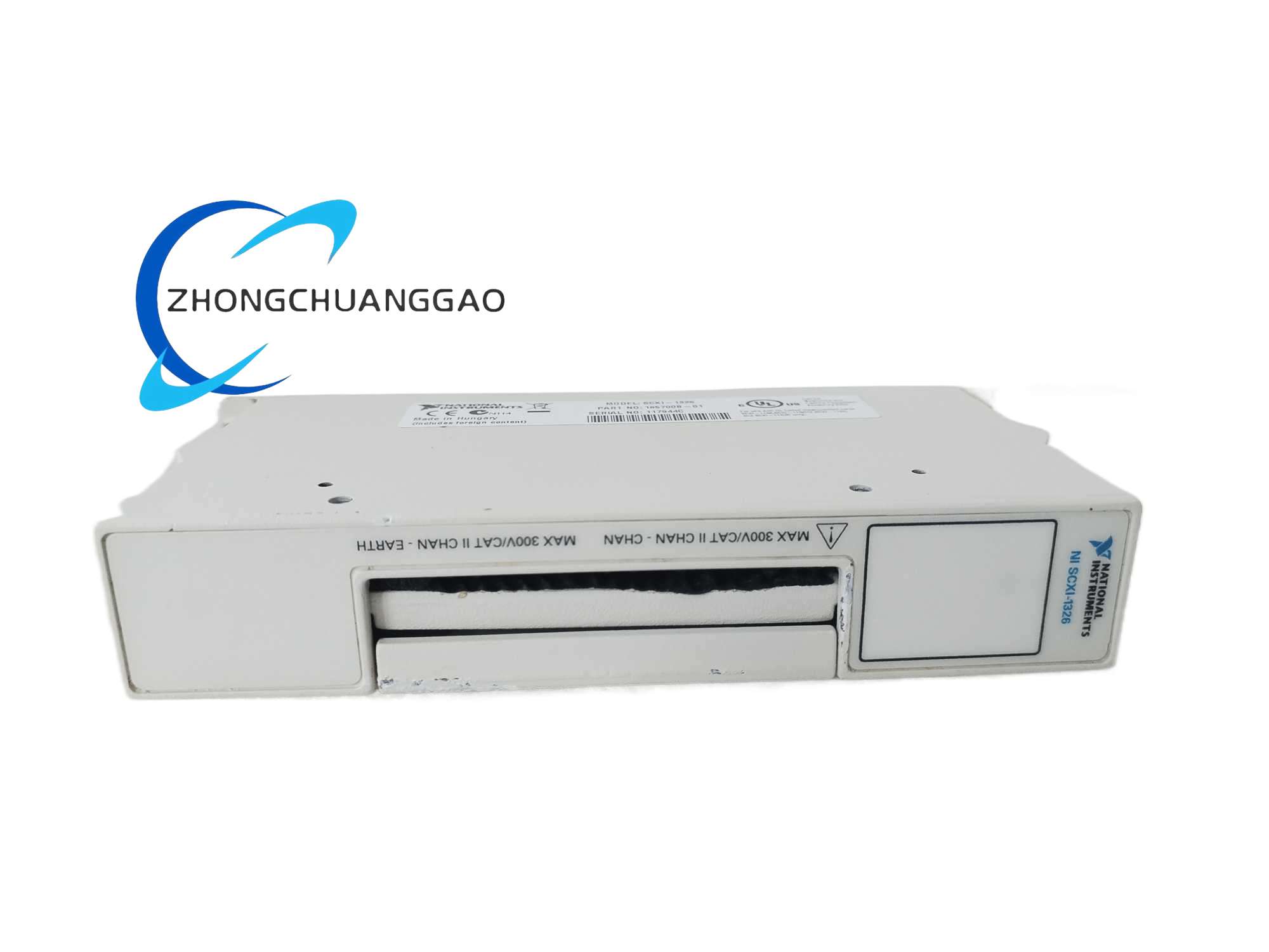
The SCXI-1326 is a high-voltage rated front-mount screw terminal block accessory designed exclusively for NI SCXI isolated digital output solid-state relay modules, fully compatible with the SCXI-1163R 32-channel relay switch module. It provides 48 isolated screw terminals separated into eight electrically independent wiring banks, supporting direct connection of industrial AC/DC high-voltage load wiring to SCXI relay modules, with built-in inter-bank electrical isolation to prevent cross-bank voltage crosstalk and short-circuit faults.
Description
Electrical Parameters
- Total Independent Screw Terminals: 48 screw terminals, divided evenly into 8 isolated wiring banks (6 terminals per bank)
- Per-Bank Terminal Layout: Each bank includes 1 VCC power terminal, 1 GND ground terminal, 4 channel signal load terminals
- Maximum Rated Working Voltage: 250 V RMS (Installation Category II per IEC 664 standard)
- Inter-Bank Isolation Rating: 250 V RMS isolation voltage between separate wiring banks and between each bank and chassis earth ground
- Supported Wiring Wire Gauge: 14–26 AWG insulated copper signal/load wire, wire insulation minimum rating 300 V, operating temperature 60°C
- Screw Terminal Tightening Torque Standard: 5–7 inch-pounds
Environmental & Physical
- Operating Temperature: 0°C ~ 50°C
- Storage Temperature: -20°C ~ 70°C
- Relative Humidity: 10% ~ 90% non-condensing
- Installation Standard: Supports DIN EN 50022 / DIN EN 50035 DIN rail auxiliary mounting and direct front-panel mating with SCXI relay modules
Functional Features
- Eight Electrically Isolated Wiring Banks: The 48 terminals are split into eight fully separated banks with high-voltage isolation barriers between each bank; users can connect mixed AC and DC load circuits to different banks without cross-bank short-circuit or voltage crosstalk risks.
- Dedicated Power & Ground Terminals Per Bank: Every wiring bank is equipped with independent VCC power supply terminal and GND ground terminal, eliminating shared power/ground wiring interference between different load circuits connected to separate banks.
- High-Voltage Safety Design (Cat II 250 V RMS Rated): All terminal hardware, plastic base and internal isolation barriers are rated for 250 V RMS industrial high-voltage load wiring, fully matching the maximum 240 V AC/DC switching capacity of the SCXI-1163R solid-state relay module.
- Integrated Full Electromagnetic Shielding Enclosure: The terminal block outer housing includes a built-in metal shielding layer to suppress external cabinet EMI interference that may induce false relay trigger signals in digital load wiring.
- Hinged Safety Protective Cover: Transparent flame-retardant plastic hinged cover fully encloses all live high-voltage screw terminals after wiring completion, preventing accidental human contact with live high-voltage terminals and conductive foreign matter short-circuit hazards.
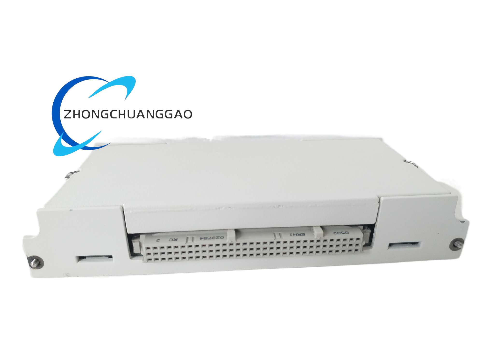
- Direct Plug-And-Mate SCXI Relay Module Interface: Rear molded mating connector precisely aligns with the front I/O connector of SCXI digital relay modules (SCXI-1163R); two locking thumbscrews secure the terminal block firmly to the module front panel without specialized assembly tools.
Working Principle
AC or DC high-voltage load wiring from industrial field actuators (solenoid valves, indicator lamps, small motors) is stripped to standard insulation length and inserted into the corresponding channel load screw terminals of the SCXI-1326 terminal block, with each load circuit’s power supply wire connected to the bank’s dedicated VCC terminal and return ground wire connected to the bank’s GND terminal. The rear mating connector of the terminal block transmits each load channel wiring to the corresponding relay channel circuit of the mated SCXI-1163R digital relay module. The high-voltage isolation barriers between each wiring bank electrically separate load circuits with different voltage levels connected to separate banks, eliminating cross-bank voltage leakage and ground loop interference between independent load control circuits. The built-in metal shielding housing blocks cabinet electromagnetic interference from inducing stray voltage signals on load wiring that would cause false relay switching errors.
Material & Structural Characteristics
- Terminal Block Base Housing: UL94-V0 flame-retardant reinforced polycarbonate plastic base with integrated internal high-voltage isolation partitions between each wiring bank; built-in thin metal EMI shielding sheet fully lining the inner housing cavity.
- Screw Terminal Hardware: Thick tin-plated brass terminal clamping bodies and wire jaws, rated for continuous high-voltage AC/DC load current transmission, anti-oxidation and corrosion-resistant for industrial cabinet environments; steel flat-head tightening screws with standardized torque limits.
- Safety Protective Cover: Transparent flame-retardant polycarbonate hinged cover with integrated locking tabs to prevent accidental opening after installation.
- Rear Mating Connector Assembly: Molded high-temperature plastic connector housing with gold-plated copper contact pins for stable low-resistance electrical connection with SCXI relay module front I/O connectors; two metal thumbscrews for front-panel locking.
- Auxiliary DIN Rail Mounting Bracket: Removable metal DIN rail adapter bracket for independent DIN rail cabinet mounting when not directly mated to an SCXI relay module.
Installation Requirements
- Module Compatibility Limitation: Exclusively designed for NI SCXI isolated digital relay modules (SCXI-1162, SCXI-1162HV, SCXI-1163, SCXI-1163R); incompatible with analog input or RF multiplexer SCXI modules.
- High-Voltage Wire Specification Mandate: All load signal wires connected to the terminal block must have insulation rated minimum 300 V Cat II, wire operating temperature rating ≥60°C; wire gauge limited to 14–26 AWG solid/stranded copper wire.
- Per-Bank Independent Power Wiring Rule: Do not share VCC or GND wiring between separate wiring banks; each bank’s load power supply and ground return must connect exclusively to that bank’s dedicated VCC and GND terminals to eliminate cross-bank electrical interference.
- Mating Locking Procedure: Align the rear connector of SCXI-1326 with the front I/O connector of SCXI-1163R, fully insert the mating connector, then manually tighten the top and bottom thumbscrews to lock the terminal block securely to the module front panel.
- Grounding Safety Specification: Connect the terminal block chassis ground lug to the control cabinet protective earth ground bar using a minimum 1.5 mm² copper ground wire to provide a low-impedance fault current discharge path for high-voltage load circuit short-circuit events.
- Post-Wiring Safety Inspection: After completing all load wiring and tightening terminal screws to specified torque, close the transparent protective cover and fasten the cover locking tabs to isolate all live high-voltage screw terminals.
Application Scenarios
- Industrial automation solenoid valve, indicator light, small motor high-voltage load wiring terminal, paired with SCXI-1163R relay switch modules.
- Power system test bench high-voltage relay switching load wiring interface.
- Building automation HVAC actuator, lighting zone control high-voltage wiring terminal accessory.
- Laboratory automated test equipment AC/DC load bank multi-channel switching wiring terminal block.
- Energy equipment auxiliary safety relay control circuit high-voltage isolated wiring terminal.
Operation & Usage Precautions
- High-Voltage Electric Shock Hazard Warning: All load wiring installation, modification or disconnection must be performed after fully cutting off both the SCXI chassis control power supply and all field load power supply; live high-voltage terminal contact creates severe electric shock hazards to operators.
- Screw Terminal Torque Control: Tighten terminal screws strictly within the 5–7 in-lb torque range; over-tightening cracks the plastic isolation partitions between wiring banks and deforms brass terminal jaws; under-tightening causes loose load wiring, leading to intermittent circuit open faults and terminal overheating under continuous load current.
- Cross-Bank Voltage Mixing Restriction: Avoid connecting load circuits with drastically different voltage levels (e.g., 24 V DC low-voltage control circuits and 220 V AC high-voltage actuator circuits) to adjacent wiring banks without adequate insulation separation; voltage leakage across isolation barriers may induce stray voltage faults in low-voltage circuits.
- No Unauthorized Modification Prohibition: Do not drill, cut or modify the terminal block plastic base, internal isolation partitions or built-in metal shielding layer; structural modification destroys high-voltage isolation and EMI shielding performance, creating permanent safety hazards.
- Cleaning Maintenance Restrictions: Only clean dust and debris from the terminal block using dry non-metallic anti-static brushes; never use water, liquid solvents or conductive cleaning sprays to wipe high-voltage screw terminals, which will cause terminal oxidation and electrical short-circuit failure under high-voltage load conditions.
- Overvoltage Protection Limit: Do not connect load circuits with working voltage exceeding 250 V RMS to any terminal bank; overvoltage will break down the internal isolation barriers between wiring banks, causing permanent terminal block damage and catastrophic cross-circuit short-circuit faults.
Reviews
There are no reviews yet.