
Product Short Description
Product Introduction
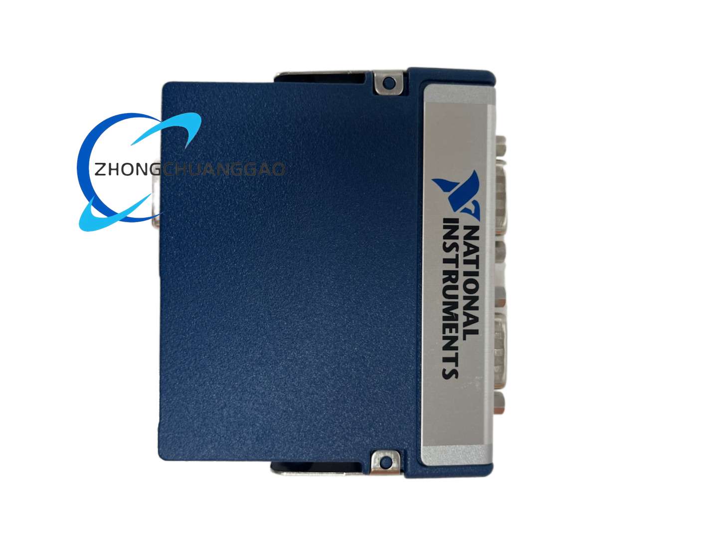
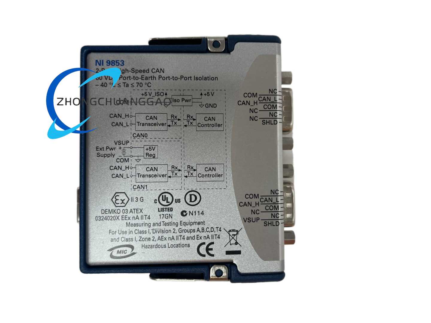
The NI 9853 is a multi-channel CAN/CAN FD bus communication C Series module developed for CompactRIO real-time embedded control systems, providing 2 independent galvanically isolated CAN bus communication channels compatible with standard CAN 2.0 A/B and high-speed CAN FD protocols. Each channel integrates built-in isolated CAN transceivers, termination resistance switches and EMC surge protection circuits, supporting real-time high-speed data interaction between CompactRIO controllers and industrial CAN bus field devices such as automotive ECUs, servo drives, battery management systems and industrial robots.
Description
Core Technical Specifications & Performance Parameters
- CAN Bus Channel Quantity: 2 fully independent galvanically isolated CAN communication channels
- Supported Bus Protocols: CAN 2.0A (11-bit identifier), CAN 2.0B (29-bit extended identifier), CAN FD high-speed flexible data rate protocol
- Programmable Baud Rate Range: Standard CAN baud rate from 1 kbit/s to 1 Mbit/s; CAN FD data phase baud rate up to 8 Mbit/s
- Channel Isolation Performance: 2500 Vrms channel-to-chassis galvanic isolation, 1000 Vrms channel-to-channel isolation
- Built-in Termination Resistance: Software-controlled 120Ω CAN bus termination resistor for each channel, can be enabled or disabled via program commands without manual hardware jumper adjustment
- Transceiver Protection Circuits: Each channel integrates ESD electrostatic discharge protection, ±60 V bus line short-circuit protection, reverse power supply connection protection
- Module Power Consumption: Maximum 350 mW power consumption when both channels operate at full load communication state
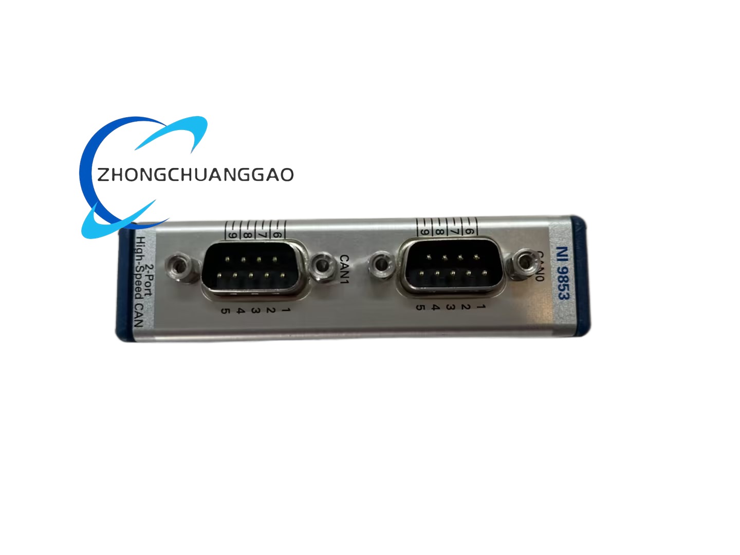
- Connector Form: Front panel 9-pin D-SUB male industrial connector, two independent D-SUB ports for two CAN channels respectively
- Environmental Rating Parameters
- Continuous operating ambient temperature: -40℃ ~ +70℃
- Relative humidity range for operation and storage: 5%RH ~ 95%RH non-condensing
- Shock resistance: 30 g half-sine pulse impact for 11 ms; vibration resistance: 5 g RMS random vibration from 10 Hz to 500 Hz
- Ingress protection level: IP40 when installed inside sealed CompactRIO chassis
Function & Feature Highlights
- Two independent isolated CAN bus channels support simultaneous connection of two different CAN bus network segments; high isolation voltage completely eliminates ground loop communication failure caused by different ground potentials between field CAN devices and control cabinets
- Full compatibility with CAN FD high-speed data transmission protocol; supports data frame length up to 64 bytes, greatly improving real-time data transmission efficiency compared with traditional standard CAN bus with maximum 8-byte data frames
- Programmable software-controlled 120Ω bus termination resistor for each channel; users can switch the resistor status through LabVIEW FPGA program according to the actual bus wiring length without disassembling the module or modifying hardware jumpers on site
- Built-in comprehensive bus fault diagnosis functions including bus off state detection, bus short-circuit alarm, transceiver over-temperature protection and frame error count statistics; all fault state data can be uploaded to upper monitoring software for real-time fault warning and troubleshooting
- Native full compatibility with all CompactRIO real-time industrial controller chassis; all CAN bus frame sending, receiving, filtering and bus fault monitoring logic can be customized and executed with microsecond-level deterministic delay on the chassis FPGA chip
- Standard C Series compact modular design allows dense installation alongside analog measurement, digital I/O and motion control modules on a single CompactRIO chassis to realize integrated multi-bus industrial embedded control platforms
- Industrial-grade metal-shielded 9-pin D-SUB connectors with threaded locking screws; the metal shielding shell of the connector is connected to the module internal isolation ground to suppress external electromagnetic interference on CAN bus differential signal lines
Working Principle
The NI 9853 module is inserted into the I/O slot of the CompactRIO chassis and connected to the chassis internal high-speed backplane bus, obtaining DC operating power and digital control instructions from the chassis real-time processor and FPGA chip. Each independent CAN channel of the module is equipped with a dedicated isolated CAN transceiver chip; the isolation transformer inside the transceiver completely separates the low-voltage digital control circuit inside the module and the external high-voltage CAN bus differential signal circuit to block common-mode voltage interference between different network segments. When the CompactRIO FPGA chip needs to send data frames to external CAN bus devices, the FPGA transmits frame data including identifier, data length and payload to the module’s onboard communication control chip through the backplane bus. The control chip converts digital frame data into differential CAN bus electrical signals through the isolated transceiver chip, which are transmitted to external field CAN devices via the CAN_H and CAN_L signal lines of the front D-SUB connector. When external CAN devices send data frames to the CompactRIO controller, the differential electrical signals on the CAN bus lines are received by the isolated transceiver chip of the module, converted into digital frame data, and temporarily stored in the onboard multi-frame FIFO receiving buffer memory. The buffered frame data is transmitted to the CompactRIO chassis FPGA chip through the high-speed backplane bus; users run customized LabVIEW FPGA logic to perform frame identifier filtering, data parsing, bus communication rate adjustment and bus fault state judgment. The software-controlled 120Ω termination resistor circuit is connected in parallel to the CAN_H and CAN_L differential signal lines of each channel; the FPGA chip sends digital switch control signals to enable or disable the resistor according to program configuration commands to match the impedance matching requirements of different CAN bus wiring lengths. The built-in multi-layer protection circuit continuously monitors the voltage level of CAN_H and CAN_L bus lines; when bus short-circuit, reverse voltage or excessive ESD surge events are detected, the transceiver chip automatically enters bus off protection mode, cuts off bus signal transmission and sends digital fault alarm information to the chassis control system.
Material Composition & Structural Features
- Housing Material: Black flame-retardant UL94-V0 industrial ABS plastic shell, built-in anti-electromagnetic interference conductive metal lining
- Isolation Components: Miniature high-voltage isolation transformers independently configured for each CAN channel, high-temperature resistant insulating epoxy filling between transformer primary and secondary windings to meet 2500 Vrms isolation withstand voltage requirements
- Internal Circuit Board: Multi-layer digital communication PCB, separate digital ground plane and bus transceiver isolation ground plane to prevent internal digital switching noise from interfering with CAN bus differential signal transmission
- Core Electronic Components: Isolated CAN/CAN FD transceiver chips, FIFO multi-frame receiving and sending buffer memory chips, digital bus termination resistor control switch chips, ESD and surge protection TVS diode arrays, bus fault detection comparator chips
- Chassis Mounting Structure: Standard C Series horizontal slide rail locking mechanism; the module slides into the empty I/O slot of the CompactRIO chassis, and the metal locking buckle at the rear is clamped to the edge of the chassis slot to ensure stable electrical contact between the module edge connector and the chassis backplane gold fingers under continuous mechanical vibration
- Front Panel Connector Assembly: Two independent metal-shielded 9-pin D-SUB male industrial connectors with threaded locking screws; the metal shielding shell of each connector is electrically connected to the module internal isolation ground circuit through conductive spring shrapnel
Installation Requirements
- Chassis Mounting Operation Steps: Slide the NI 9853 module horizontally into the empty C Series I/O slot of the CompactRIO industrial controller chassis, push the module completely backward until the rear metal locking buckle clicks to lock, ensuring full electrical contact between the module edge connector and the chassis backplane bus gold fingers
- CAN Bus Field Wiring Specifications
- Cable Selection: Use dedicated CAN bus shielded twisted-pair cable for all external CAN bus wiring; the metal shielding layer of the cable is single-end grounded inside the control cabinet to suppress external electromagnetic induction noise generated by on-site motors and frequency converters
- D-SUB Connector Wiring Operation: Crimp the stripped CAN_H and CAN_L wire ends to the corresponding pin terminals of the 9-pin D-SUB connector, assemble the metal shielding shell of the connector, tighten the two threaded locking screws clockwise to fix the connector tightly on the module front panel port
- Bus Termination Configuration Rules: Enable the built-in 120Ω termination resistor of the module channel only when the module is installed at the physical two ends of the entire CAN bus network; disable the termination resistor for all intermediate node devices on the bus to avoid bus signal reflection and communication frame loss
- Environmental Installation Restrictions
- The CompactRIO chassis equipped with the NI 9853 module must be installed inside a fully sealed indoor industrial electrical control cabinet; installation positions with direct water splashing, corrosive chemical gas, conductive metal dust or direct high-temperature heat radiation are forbidden
- Maintain a minimum spacing of 25 mm between the NI 9853 module and high-power heat-generating components such as power supply modules and frequency converters inside the cabinet to avoid excessive ambient temperature affecting CAN bus transceiver communication stability
- High-Vibration Industrial Environment Installation Rules
- For automotive test benches, industrial robot production lines and other long-term high-vibration working environments, use cable ties to fix all CAN bus cables to the cabinet internal wiring brackets and install cable strain relief clamps at the D-SUB connector ends to prevent wire pulling and connector loosening under sustained mechanical vibration
- Every quarter, visually inspect the tightness of the D-SUB connector threaded locking screws to eliminate unstable communication frame loss caused by loose connector contact
- Altitude Operation Limits: The module supports stable continuous operation at altitudes up to 2000 meters above sea level; for high-altitude industrial test sites above 2000 meters, additional heat dissipation fans need to be installed inside the control cabinet to reduce ambient operating temperature and prevent transceiver over-temperature communication failure
Application Scenarios
- Automotive electronic test benches: Vehicle ECU communication simulation, battery management system BMS CAN FD data interaction, new energy vehicle motor controller real-time data monitoring
- Industrial automation equipment control: Multi-axis servo drive CAN bus motion control, industrial robot controller real-time bus communication, automated production line distributed sensor network data transmission
- Energy storage and new power equipment monitoring: Lithium battery energy storage cabinet BMS multi-node CAN bus data collection, wind turbine generator unit CAN FD bus fault monitoring, photovoltaic power station distributed combiner box communication
- Aerospace vehicle embedded control systems: UAV flight controller CAN bus real-time data interaction, aerospace ground test equipment multi-device bus communication synchronization
- Heavy machinery and construction equipment monitoring: Excavator, crane hydraulic system controller CAN bus data logging, mining equipment distributed safety sensor network communication
- Laboratory multi-device integrated test platforms: Multi-channel CAN bus signal simulation, industrial communication protocol compatibility testing, real-time bus frame capture and data analysis
Operation & Maintenance Precautions
- All external CAN bus wiring modification, D-SUB connector disassembly and module replacement operations must be performed after completely cutting off the main DC power supply of the CompactRIO chassis; live wiring will generate transient voltage surges that permanently damage the internal isolated CAN transceiver chip
- Strictly follow CAN bus wiring specifications to distinguish CAN_H and CAN_L differential signal lines; cross wiring of CAN_H and CAN_L will cause complete bus communication failure and trigger the module bus off fault protection state
- Do not connect the CAN bus signal lines to external high-voltage power supply circuits; overvoltage input exceeding ±60 V will break down the internal transceiver protection circuit and render the communication channel permanently invalid
- Avoid long-term continuous operation when the ambient temperature of the cabinet exceeds +70℃; excessive high temperature will cause the CAN transceiver chip to enter over-temperature bus off protection mode, interrupting normal bus data transmission
- During scheduled annual equipment maintenance, use dry compressed air to blow away dust accumulated on the module shell and front D-SUB connectors; dust accumulation will cause connector pin oxidation and unstable bus communication frame reception
- When replacing a faulty NI 9853 module, confirm that the chassis power supply is completely disconnected before sliding out the faulty module; after installing a new spare module, re-download the LabVIEW FPGA communication program and reconfigure the baud rate, termination resistor status and frame filtering rules of each CAN channel before restarting the bus communication system
Reviews
There are no reviews yet.