Product Short Description
Product Category: Intrinsically Safe Barrier (2-Wire, 4–20 mA, Passive)
Barrier Type: Zener Barrier with Galvanic Isolation
Number of Channels: 1 channel (single loop)
Input Side (Safe Area): 4–20 mA DC from DCS/PLC/transmitter power supply
Output Side (Hazardous Area): 4–20 mA DC to field transmitter
Isolation Voltage: 1500 V DC (50/60 Hz, 1 minute) between input, output, and earth
Description
Intrinsic Safety Parameters:
- Uo (Open Circuit Voltage): 28.0 V DC
- Io (Short Circuit Current): 93 mA DC
- Po (Maximum Power): 1.30 W
- Co (Maximum Capacitance): 83 nF
- Lo (Maximum Inductance): 0 mH (inductive loads not permitted on this barrier)
Supply Voltage (Safe Side): 24 VDC nominal, operating range 18–32 VDC
Maximum Loop Resistance (Safe Side): 600 Ω (including wiring resistance)
Maximum Loop Resistance (Hazardous Side): 300 Ω (including transmitter and wiring)
Output Current Range: 4–20 mA DC (proportional to input signal)
Voltage Drop Across Barrier (at 20 mA): Less than 2.5 V DC
Accuracy: ±0.1% of span (at 20 mA)
Response Time: Less than 10 ms (typical)
Thermal Drift: Less than ±0.02% of span per °C
Operating Temperature Range: -20°C to +60°C (-4°F to +140°F)
Storage Temperature Range: -40°C to +85°C (-40°F to +185°F)
Ambient Humidity: 5% to 95% RH, non-condensing
Altitude: Up to 2000 m (6562 ft) above sea level (derate above 2000 m per IEC 60079-11)
Vibration: 5 g, 10–55 Hz (operating)
Shock: 15 g, 11 ms half-sine
Ingress Protection: IP20 (DIN rail enclosure, indoor use only)
Enclosure Rating: Non-hazardous area only — barrier must be installed in a safe location
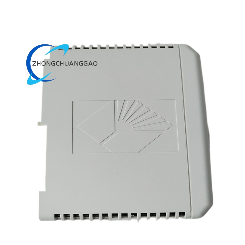
Housing Material: Polycarbonate (UL 94 V-0 rated) — flame retardant
Terminal Blocks: Screw-clamp terminals, tin-plated brass contacts
DIN Rail: Standard 35 mm top-hat DIN rail (EN 60715), snap-in mounting
Internal Components:
- Zener diodes: Silicon, hermetically sealed — clamp voltage to safe levels
- Current-limiting resistors: Metal film, 1% tolerance, flameproof
- Isolation transformer: Ferrite core, galvanic isolation between safe and hazardous sides
- Fuses: 250 mA, fast-acting, ceramic body (one per channel, user-replaceable)
Grounding Terminal: Dedicated earth terminal, green/yellow, 4 mm² minimum wire size
Weight: Approximately 0.12 kg (0.26 lbs)
Dimensions (approximate): 90 mm × 22.5 mm × 112 mm (W × D × H) excluding DIN rail
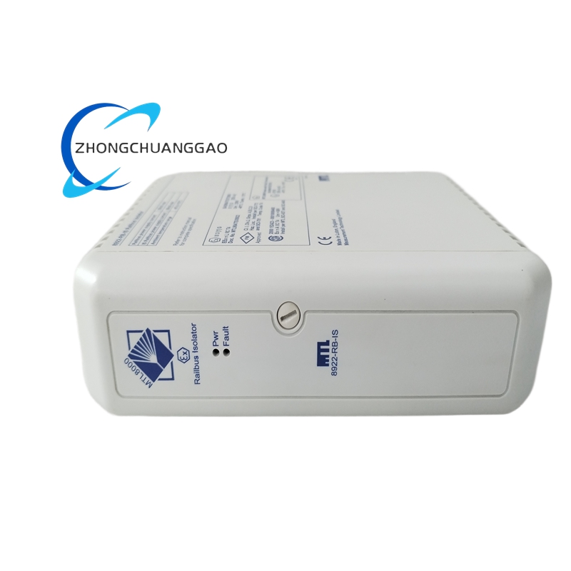
Structure:
- Slim-profile DIN rail module (22.5 mm width) — saves panel space
- 2 screw-clamp terminal blocks: one for safe side (input), one for hazardous side (output)
- 1 fuse holder with visible fuse status indicator
- 1 LED indicator: green = power ON, red = fuse blown or fault
- 1 grounding terminal: green/yellow screw, 4 mm² wire capacity
- Snap-in DIN rail mounting clips on top and bottom
- Clear labeling: channel number, input/output polarity, hazardous area marking
Working Principle:
The MTL 8922-RB-IS uses a zener diode barrier circuit combined with a galvanic isolation transformer to limit energy in the hazardous area. On the safe area side, the 4–20 mA signal from the DCS/PLC passes through a current-limiting resistor and then through the isolation transformer primary winding. The transformer provides galvanic isolation (1500 V DC) between the safe and hazardous sides. On the hazardous area side, the signal is rectified and regulated by zener diodes that clamp the voltage to 28.0 V DC maximum and limit the current to 93 mA maximum. A 250 mA fuse provides secondary overcurrent protection. If a fault occurs (short circuit or ground fault in the hazardous area), the fuse blows, disconnecting the hazardous area completely. The zener diodes ensure that even with a single fault, the energy delivered to the hazardous area remains below the minimum ignition energy (MIE) of the surrounding atmosphere.
Key Features:
- Intrinsically safe certification — safe for use in Zone 0, Zone 1, Zone 2 (gas) and Zone 20, Zone 21, Zone 22 (dust)
- Galvanic isolation (1500 V DC) — eliminates ground loops and protects against transient voltages
- Single-channel, 2-wire, 4–20 mA — supports passive (loop-powered) transmitters only
- DIN rail mounting — standard 35 mm rail, snap-in installation
- User-replaceable fuse (250 mA) — field maintenance without removing the barrier from the rail
- LED status indicator — visual confirmation of power and fuse status
- Wide supply voltage range (18–32 VDC) — compatible with most DCS/PLC power supplies
- Low voltage drop (under 2.5 V at 20 mA) — minimal impact on loop power budget
Advantages:
- Certified for Zone 0 / Zone 20 — the highest level of intrinsic safety, suitable for the most hazardous environments
- Galvanic isolation — eliminates ground loops, reduces EMI, and protects control room equipment from hazardous area faults
- Slim DIN rail form factor (22.5 mm) — fits in crowded control panels where space is limited
- Low power loss (under 2.5 V drop) — maximizes available loop power for field transmitters
- User-replaceable fuse — quick fault recovery without special tools
- Passive transmitter support — works with all 2-wire, loop-powered 4–20 mA transmitters (pressure, temperature, level, flow)
- Wide temperature range (-20°C to +60°C) — suitable for outdoor control panels and unheated enclosures
Applicable Industries:
- Oil & Gas (Upstream / Midstream / Downstream) — wellhead pressure, flow measurement, tank level sensing in refineries, pipelines, and offshore platforms
- Chemical / Petrochemical — process variable monitoring in reactor vessels, distillation columns, and storage tanks
- Pharmaceutical — cleanroom-compatible barrier for process instrumentation in hazardous solvent environments
- Mining / Metals — gas detection, dust monitoring, and process control in underground and surface operations
- Power Generation — hydrogen cooling monitoring, fuel gas detection in gas turbines and boilers
- Food & Beverage — flammable solvent monitoring in flavor extraction and ethanol production
- Water / Wastewater — methane and hydrogen sulfide detection in digesters and sewers
Model Series:
| Model Number | Channels | Signal Type | Isolation | Key Feature |
|---|---|---|---|---|
| 8922-RB-IS | 1 | 4–20 mA (2-wire, passive) | Yes (1500 V DC) | DIN rail, Zone 0/20 |
| 8922-RC-IS | 1 | 4–20 mA (2-wire, passive) | Yes (1500 V DC) | DIN rail, compact |
| 8924-RB-IS | 2 | 4–20 mA (2-wire, passive) | Yes (1500 V DC) | Dual channel, DIN rail |
| 8932-RB-IS | 1 | 4–20 mA (4-wire, active) | Yes (1500 V DC) | Active transmitter support |
| 8934-RB-IS | 2 | 4–20 mA (4-wire, active) | Yes (1500 V DC) | Dual channel, active |
| 8962-RB-IS | 1 | HART (4–20 mA + digital) | Yes (1500 V DC) | HART communication support |
Hazardous Area Certifications:
| Certification | Zone / Division | Gas Group | Dust Class | Temperature Class |
|---|---|---|---|---|
| ATEX | Zone 0, Zone 1, Zone 2 | IIA, IIB, IIC | 20, 21, 22 | T6 (85°C max surface) |
| IECEx | Zone 0, Zone 1, Zone 2 | IIA, IIB, IIC | 20, 21, 22 | T6 |
| UL / CSA | Class I, Division 1, Division 2 | A, B, C, D | Class II, Division 1, Division 2 | T6 |
| FM | Class I, Division 1, Division 2 | A, B, C, D | Class II, Division 1, Division 2 | T6 |
| INMETRO | Ex ia IIC T6 | — | — | T6 |
| NEPSI | Ex ia IIC T6 | — | — | T6 |
Installation Requirements:
- Install the barrier in a safe (non-hazardous) area — typically the control room or a safe zone panel
- Mount on a standard 35 mm DIN rail (EN 60715) using the snap-in clips
- Connect the safe side terminals to the DCS/PLC analog output and 24 VDC power supply positive
- Connect the hazardous side terminals to the field transmitter using intrinsically safe cable (blue sheath, per IEC 60079-14)
- Connect the grounding terminal to the panel earth bar using 4 mm² minimum green/yellow wire
- Ensure the total loop resistance (safe side + hazardous side + barrier) does not exceed 600 Ω
- Verify the transmitter is a 2-wire, passive (loop-powered) type — active (4-wire) transmitters require model 8932-RB-IS
- Do not connect the barrier to inductive loads (solenoid valves, relays) — model 8922-RB-IS supports resistive loads only (Co = 83 nF, Lo = 0 mH)
- Label all cables with “Intrinsically Safe — IS” markings per IEC 60079-14
Usage Precautions:
- Do not install the barrier in a hazardous area — it must be located in a safe area (Zone 2 or non-classified)
- Do not exceed the maximum loop resistance of 600 Ω — this will cause the transmitter to lose power and the signal to drop below 4 mA
- Do not connect inductive loads (solenoids, relays, motors) to this barrier — it is designed for resistive loads only (transmitters); inductive loads require a different barrier (e.g., MTL 8942)
- Do not bypass or remove the fuse — the fuse is the primary overcurrent protection; removing it eliminates intrinsic safety
- Do not apply voltage exceeding 32 VDC to the safe side — this will exceed the Uo rating (28.0 V) and compromise intrinsic safety
- Do not use non-IS-rated cable on the hazardous side — standard cable lacks the blue sheath and energy-limiting characteristics required for hazardous areas
- Replace the fuse immediately if it blows — use only the specified 250 mA, fast-acting, ceramic fuse (MTL part number 8922-FUS-001)
- Do not operate the barrier above +60°C — zener diode clamping voltage increases with temperature, which can exceed safe levels
- Verify the barrier model matches the transmitter type — passive (2-wire) transmitters use 8922-RB-IS; active (4-wire) transmitters use 8932-RB-IS
- Perform annual inspection of the barrier, fuse, and terminal connections per IEC 60079-14 and local regulations
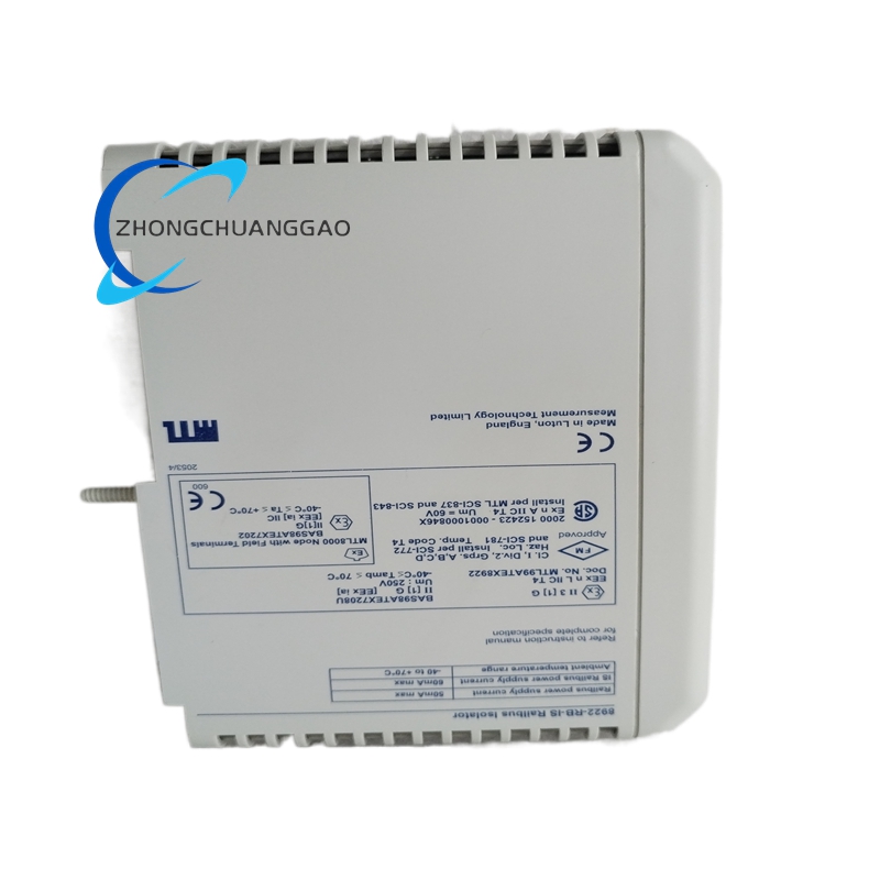
Certifications:
- ATEX: II 2G Ex ia IIC T6 Ga (Zone 0, 1, 2) / II 2D Ex ia IIIC T135°C Da (Zone 20, 21, 22)
- IECEx: Ex ia IIC T6 Ga / Ex ia IIIC T135°C Da
- UL Listed: File E156817 — Class I, Division 1, Groups A, B, C, D; Class II, Division 1, Groups E, F, G
- CSA Certified: File LR42403 — Class I, Division 1, Groups A, B, C, D; Class II, Division 1, Groups E, F, G
- CE Marked: ATEX Directive 2014/34/EU, EMC Directive 2014/30/EU, Low Voltage Directive 2014/35/EU
- FM Approved: Class I, Division 1, Groups A, B, C, D; Class II, Division 1, Groups E, F, G
- INMETRO: Ex ia IIC T6
- NEPSI: Ex ia IIC T6
- RoHS Compliant: Directive 2011/65/EU
- REACH Compliant: Regulation EC 1907/2006
Documentation Reference:
- MTL 8900 Series Installation Manual (Document 8900-IM-001)
- MTL 8922 Technical Data Sheet (Document 8922-TDS-001)
- MTL Intrinsic Safety Design Guide (Document 8900-ISD-001)
- MTL Hazardous Area Wiring Practices (Document 8900-HW-001)
- MTL Barrier Selection Guide (Document 8900-SG-001)
Replacement Parts:
| Part Number | Description |
|---|---|
| 8922-FUS-001 | Fuse, 250 mA, fast-acting, ceramic body |
| 8922-TB-001 | Terminal block assembly, safe side |
| 8922-TB-002 | Terminal block assembly, hazardous side |
| 8922-LED-001 | LED indicator board, green/red |
| 8922-TR-001 | Isolation transformer assembly |
| 8922-ZN-001 | Zener diode assembly |
| 8922-GR-001 | Grounding terminal assembly |
| 8922-RL-001 | DIN rail mounting clip set |
Reviews
There are no reviews yet.