Product Short Description
Product Overview:
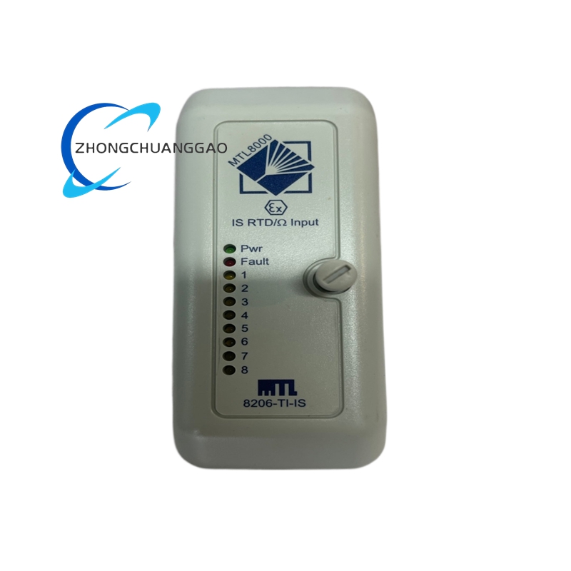
The MTL 8206-TI-IS is a dual-channel galvanically isolated Intrinsically Safe (IS) barrier from the MTL 8200 Series. It is designed to deliver safe power and signal conditioning to two independent 4–20 mA current-loop field instruments in hazardous area zones. The “TI” designation indicates transistor isolated, meaning each channel uses active electronic isolation rather than passive Zener-based barriers. The “IS” confirms full Intrinsic Safety certification for use in explosive atmospheres.
Description
Product Category: Intrinsically Safe Barrier — Dual Channel, Transistor Isolated, 4–20 mA
Function:
Limits electrical energy (voltage, current, power) delivered to field instruments in Zone 0, Zone 1, or Zone 2 hazardous areas, ensuring that under normal or single-fault conditions, the energy is insufficient to ignite a flammable atmosphere. Provides galvanic isolation between channels and between safe area and hazardous area.
Technical Specifications:
| Parameter | Specification |
|---|---|
| Part Number | 8206-TI-IS |
| Manufacturer | Eaton / MTL Instruments |
| Series | MTL 8200 |
| Type | Dual-Channel Intrinsically Safe Barrier |
| Isolation Type | Transistor Isolated (Active Electronic Isolation) |
| Number of Channels | 2 (Dual Channel) |
| Input Signal | 4–20 mA (2-wire transmitters) |
| Output to Hazardous Area | 4–20 mA limited to IS parameters |
| Supply Voltage (Input) | 24 VDC nominal (18–30 VDC range) |
| Output Voltage (to field device) | 12 VDC maximum (open circuit) |
| Output Current (to field device) | 20 mA maximum |
| Output Power (per channel) | 1.3 W (Uo × Io = 28V × 46mA = 1.3W typical) |
| Isolation Voltage | 500 VAC RMS (channel-to-channel, channel-to-ground) |
| Response Time | < 10 ms |
| Operating Temperature | -20°C to +60°C (-4°F to +140°F) |
| Storage Temperature | -40°C to +85°C (-40°F to +185°F) |
| Relative Humidity | 5% to 95% non-condensing |
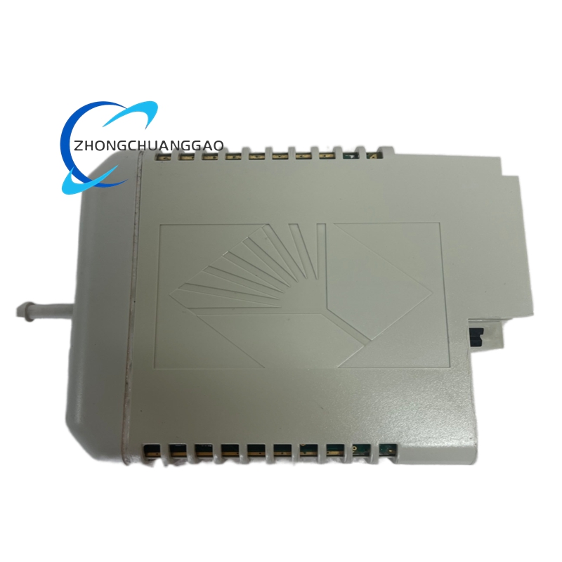
| Mounting | DIN Rail (35 mm TS 35) |
| Width | 12.5 mm (0.49 in) per channel — 25 mm total |
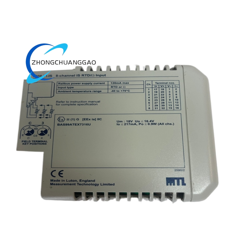
| Certification | ATEX, IECEx, FM, CSA, CENELEC, INMETRO |
| Hazardous Area Classification | Zone 0, Zone 1, Zone 2 (Gas); Zone 20, Zone 21, Zone 22 (Dust) |
| Protection Type | Ex ia IIC T6 Ga (Gas); Ex ia IIIC T135°C Da (Dust) |
| Compliance | IEC 60079-11, IEC 60079-25, EN 60079-11, EN 60079-25, ISA 12.06.01 |
| Weight (approx.) | 0.12 kg (0.26 lb) |
Material Composition:
| Component | Material |
|---|---|
| Housing | Polycarbonate (UL94 V-0 flame retardant) |
| Terminal Blocks | Phosphor Bronze with tin plating |
| Isolation Circuitry | Optocouplers + Zener diodes + active transistors |
| DIN Rail Clip | Zinc-plated steel |
| Internal PCB | FR-4 glass epoxy with conformal coating |
| Sealing Gaskets | Silicone rubber |
| Marking Labels | Laser-etched polyester film (permanent) |
Structural Features:
- Dual-channel design — each channel is fully independent with separate input, output, and isolation circuitry
- Transistor (active) isolation — provides superior accuracy and stability compared to Zener barriers
- DIN rail mountable — fits standard 35 mm TS 35 top-hat rail
- Screw-clamp terminal connections — accepts 0.5 to 2.5 mm² (24–14 AWG) solid or stranded wire
- Channel-to-channel isolation — 500 VAC RMS ensures no cross-talk or fault propagation between channels
- LED status indicators — one per channel for power-on / fault indication
- Compact 25 mm width — fits in standard instrumentation enclosures with high channel density
- Removable terminal blocks — allows field wiring without tools
Working Principle:
- The safe-area 24 VDC power supply connects to the barrier input terminals.
- The 4–20 mA signal from the control system (DCS/PLC) enters the barrier’s input side.
- The transistor isolation circuit galvanically separates the safe area from the hazardous area using optocouplers and active regulation transistors.
- The barrier actively limits output voltage to 12 VDC max and current to 20 mA max per channel.
- The limited energy is delivered to the field instrument (transmitter) in the hazardous area.
- Under single-fault conditions (short circuit, open circuit, component failure), the barrier ensures energy remains below the minimum ignition energy (MIE) of the surrounding atmosphere.
- The Zener diode clamps provide secondary overvoltage protection as a fail-safe backup to the active transistor circuit.
Key Advantages:
- Transistor isolation (TI) delivers ±0.1% accuracy — far superior to Zener barriers (±2–5%)
- Dual independent channels — one channel failure does not affect the other
- 500 VAC isolation — meets the highest galvanic isolation requirements
- Ex ia IIC T6 Ga — certified for Zone 0 (most stringent gas classification)
- Ex ia IIIC T135°C Da — certified for Zone 20 (most stringent dust classification)
- Wide input voltage range (18–30 VDC) — tolerant of power supply fluctuations
- Fast response time (< 10 ms) — suitable for fast-loop control applications
- Low heat dissipation — active regulation wastes less energy than Zener shunt barriers
- ATEX / IECEx / FM / CSA / INMETRO — globally recognized certifications
- DIN rail form factor — standard instrumentation mounting, no special brackets required
Applicable Industries:
| Industry | Application |
|---|---|
| Oil & Gas (Upstream) | Wellhead monitoring, separator control, pipeline SCADA |
| Oil & Gas (Downstream) | Refinery process control, tank farm level measurement |
| Chemical / Petrochemical | Reactor temperature/pressure transmitters, flow meters |
| Pharmaceutical | Cleanroom process monitoring, batch reactor control |
| Mining | Gas detection transmitters, ventilation monitoring |
| Power Generation | Boiler drum level, turbine vibration sensors |
| Water / Wastewater | Chlorine gas detection, dissolved oxygen transmitters |
| Food & Beverage | Dust-prone areas (flour mills, grain silos) |
| Marine / Offshore | Engine room gas detection, cargo tank monitoring |
Compatible Field Instruments:
| Instrument Type | Connection |
|---|---|
| 2-wire 4–20 mA transmitters | Direct connection (loop-powered) |
| Temperature transmitters (RTD/TC) | 4–20 mA output |
| Pressure transmitters | 4–20 mA output |
| Level transmitters (radar/ultrasonic) | 4–20 mA output |
| Gas detectors (catalytic/IR) | 4–20 mA output |
| Flow meters (electromagnetic/vortex) | 4–20 mA output |
| Analytical instruments (pH, conductivity) | 4–20 mA output |
Installation Requirements:
- Mount on standard 35 mm TS 35 DIN rail in a safe area enclosure (Zone 2 or non-hazardous)
- Ensure minimum 10 mm clearance above and below the barrier for heat dissipation
- Connect input wiring (safe area) to terminals 1, 2 (Channel 1) and 3, 4 (Channel 2)
- Connect output wiring (hazardous area) to terminals 5, 6 (Channel 1) and 7, 8 (Channel 2)
- Use shielded twisted-pair cable for hazardous area connections — ground shield at safe area end only
- Maximum cable length: per IEC 60079-14 — typically 100 m (328 ft) for 4–20 mA loops (verify per installation)
- Apply anti-seize compound to DIN rail clip before mounting
- Torque terminal screws to 0.5 Nm (4.4 in-lbs) maximum
- Verify barrier ground terminal is connected to earth ground (protected earth, PE)
- Do not daisy-chain barriers — each barrier must have its own dedicated DCS/PLC input
Usage Precautions:
- Do not exceed 30 VDC input voltage — overvoltage destroys isolation circuitry
- Do not connect 3-wire transmitters — this barrier is designed for 2-wire loop-powered instruments only
- Do not exceed 20 mA output per channel — overcurrent defeats intrinsic safety
- Do not mix channels — each channel has independent IS parameters; do not cross-connect
- Replace immediately if housing is cracked, terminals are burnt, or LED indicators fail
- Perform annual inspection per IEC 60079-14 — verify terminal tightness, insulation resistance (> 100 MΩ)
- Do not operate without proper earthing — missing earth ground voids IS certification
- Do not install in direct sunlight or near heat sources > 60°C — exceeds operating temperature
- Verify loop resistance before commissioning — total loop resistance (wire + transmitter) must allow 12 VDC at 20 mA minimum
- Use only MTL-approved cables for hazardous area wiring — non-approved cables void certification
- Document installation in the hazardous area equipment register per ATEX/IECEx requirements
Cross-Reference / Equivalent Part Numbers:
| Manufacturer | Part Number |
|---|---|
| MTL (Eaton) | 8206-TI-IS |
| MTL Original | 8206TIIS |
| Pepperl+Fuchs Equivalent | KFD2-STC-Ex1.LB (single channel) |
| Turck Equivalent | IM21-14EX-I (single channel) |
| R. Stahl Equivalent | 9002/9003 (single channel) |
| Aplisens Equivalent | IS-Barrier-2CH |
Warranty:
Eaton / MTL Instruments provides a 3-year limited warranty from date of shipment against defects in materials and workmanship under normal operating conditions. Warranty does not cover damage from incorrect installation, overvoltage, or misuse.
Service Life:
15 to 20 years under normal operating conditions with annual inspection per IEC 60079-14. Replace at each major plant shutdown or if insulation resistance drops below 100 MΩ.
Documentation Reference:
- MTL 8200 Series Installation Manual — Doc No. 8200-IM-001
- Eaton Intrinsic Safety Handbook — Doc No. ISH-2024
- IEC 60079-11:2011 — Intrinsic Safety “i”
- IEC 60079-25:2020 — Intrinsic Safety “ia”
- ATEX Directive 2014/34/EU — Annex II, Module G
- IECEx Scheme — Certificate No. IECEx MTL 24.0001X
Reviews
There are no reviews yet.