
Product Short Description
Product Overview
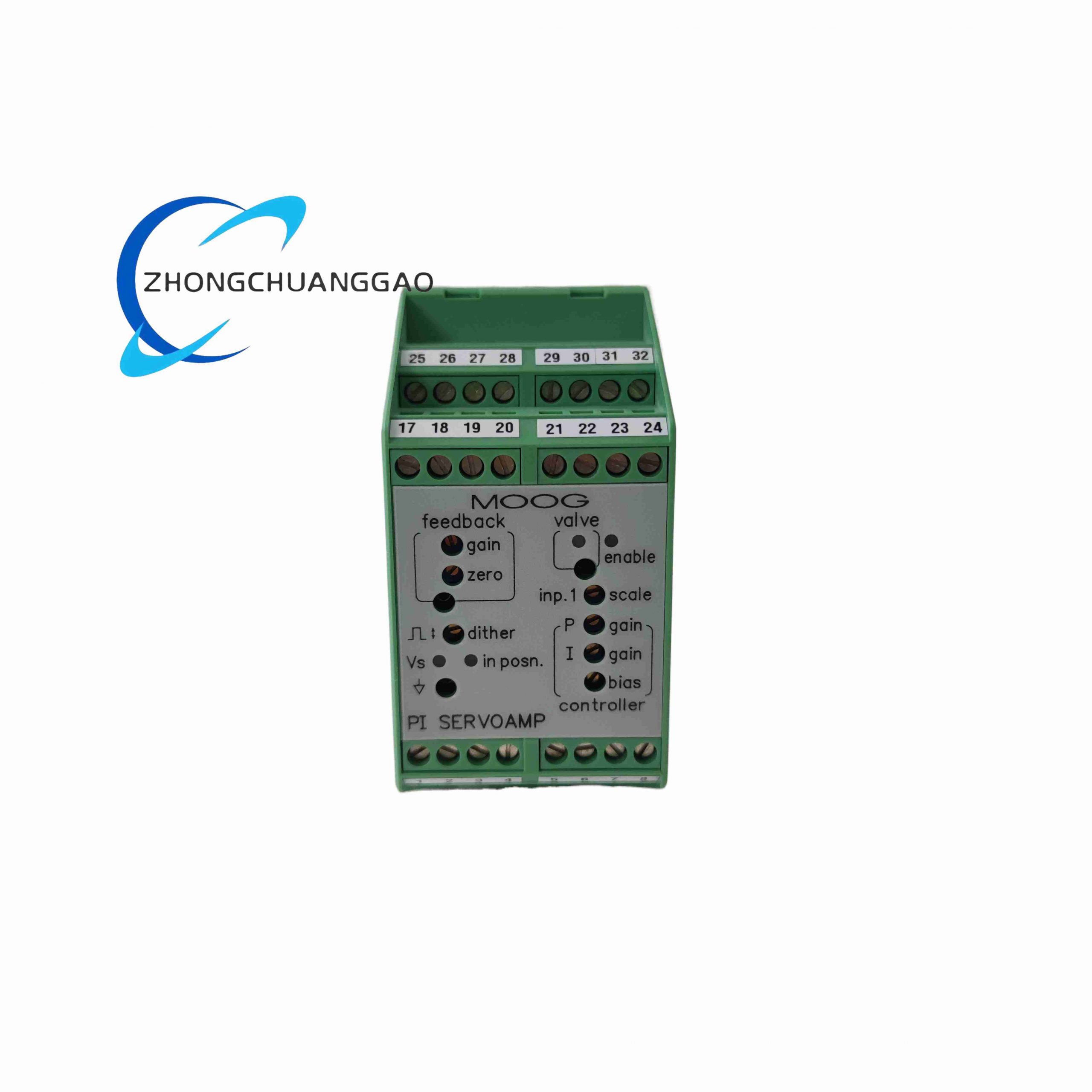
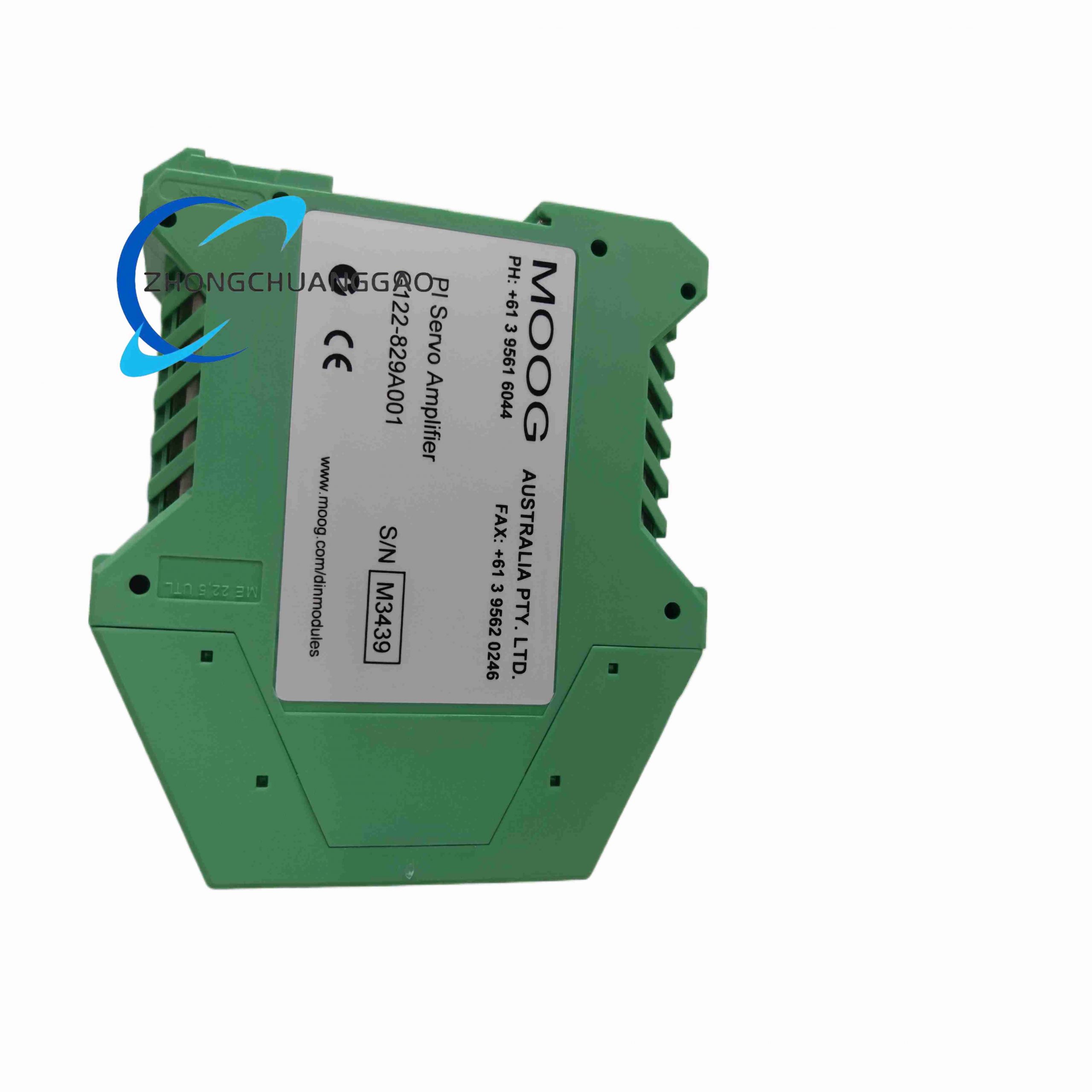
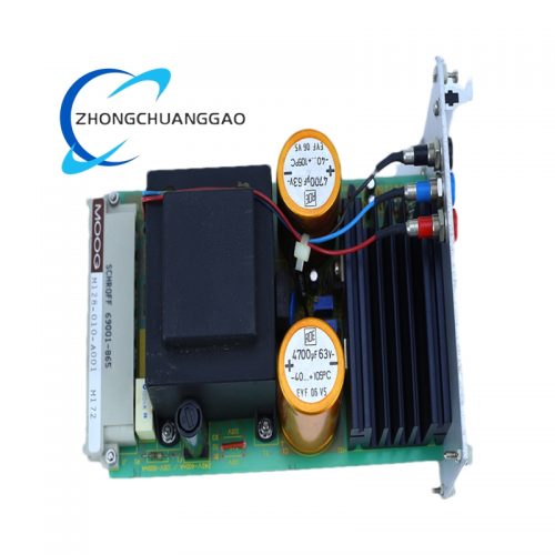
MOOG G122-829A-001 is a universal field-configurable analog servo amplifier dedicated to closed-loop hydraulic and electro-hydraulic servo valve control systems. It is an upgraded iteration of G122-829-001, adding dual differential signal input, 4–20mA analog monitoring output, and three-stage servo valve loop gain tuning function. It serves as the core signal conditioning and power drive unit between industrial motion controllers and MOOG series servo valves, widely adopted for precision closed-loop position, speed, and pressure control loops.
Description
Core Technical Specifications
- Power Supply: 24VDC auxiliary control power, 0.8A rated consumption
- Control Modes: Independent P-only, I-only, combined P+I closed-loop control (selected via internal DIP switch SW6)
- Signal Input Channels: Dual differential analog input (±10V standard), single-ended command input terminal block
- Output Signals: ±10V drive signal for servo valve coils; isolated 4–20mA monitoring output proportional to valve drive current
- Adjustment Interfaces: Front-panel multi-turn potentiometers for zero offset, loop gain, integral time constant, dead band compensation
- Response Bandwidth: Up to 30kHz control update frequency
- Environmental Parameters: Operating temperature -20°C ~ +70°C; storage -30°C ~ +85°C; humidity 5%–95% non-condensing
- Physical Dimension: 128mm(W) × 105mm(H) × 42mm(D); weight 320g; standard 35mm DIN rail form factor
- Terminal Layout: Two groups of screw terminals (Terminals 1–16 lower, 17–32 upper); dedicated test points for real-time signal measurement
Function Features
- Full user reconfigurable control algorithm to match hydraulic servo valve dynamic characteristics
- Built-in short-circuit, over-current, reverse polarity, and surge voltage protection circuits
- Visible LED status indicators for power, signal deviation, and fault alarm
- Isolated signal circuit to eliminate ground loop interference between controller and valve actuator
- Support three-stage servo valve gain calibration for large-flow proportional servo valves
- Modular design allows hot removal from DIN rail without disrupting adjacent equipment
Working Principle
- Receives analog position/speed/pressure command signals from upper PLC/motion controller via differential input terminals
- Compares command signal with position feedback signal from valve LVDT transducer to generate deviation error signal
- Internal DIP switches select proportional gain and integral integration time constant; front potentiometers fine-tune loop dynamic response
- Amplifies processed error signal into high-current ±10V drive output to actuate servo valve torque motor
- Converts drive current into isolated 4–20mA signal for remote monitoring via DCS/recorder systems
- Automatic fault interlock cuts drive output upon over-current or short-circuit to protect servo valve coils
Material & Structural Characteristics
- Outer Enclosure: Flame-retardant black ABS plastic with anti-static coating
- Internal PCB: Double-sided copper-clad fiberglass board with gold-plated signal traces
- Terminal Blocks: Nickel-plated copper screw terminals with anti-loose spring washers
- Heat Dissipation: Top and bottom vertical ventilation slots for natural convection cooling; no built-in fan
- Mounting Hardware: Integrated DIN rail snap lock clip at the bottom rear
Installation Requirements
- Mount horizontally on vertical cabinet rear plate with standard 35mm DIN rail; ensure ventilation gap ≥20mm above and below the unit
- Route command signal cables as shielded twisted pairs, separate from high-power hydraulic valve cables by ≥15cm to avoid EMI
- Torque all terminal screws to 0.6–0.8N·m; loose wiring causes signal drift and overheating
- Ground cable shielding layer at single end only to prevent circulating ground current
- Avoid installation adjacent to hydraulic power units, transformers, or high-frequency inverters
Usage Precautions
- Do not adjust internal DIP switches under live power; power off before opening the plastic cover
- Limit input differential voltage within ±12V to prevent front-end op-amp burnout
- Clean ventilation slots every 6 months to avoid dust blockage leading to over-temperature shutdown
- Store in dry warehouse with humidity below 70% if long-term idle; prevent PCB corrosion
- Match integral time constant to system hydraulic stiffness: short integral time for rigid hydraulic loops, longer integral time for flexible low-stiffness systems
Reviews
There are no reviews yet.