
Product Short Description
Product Overview
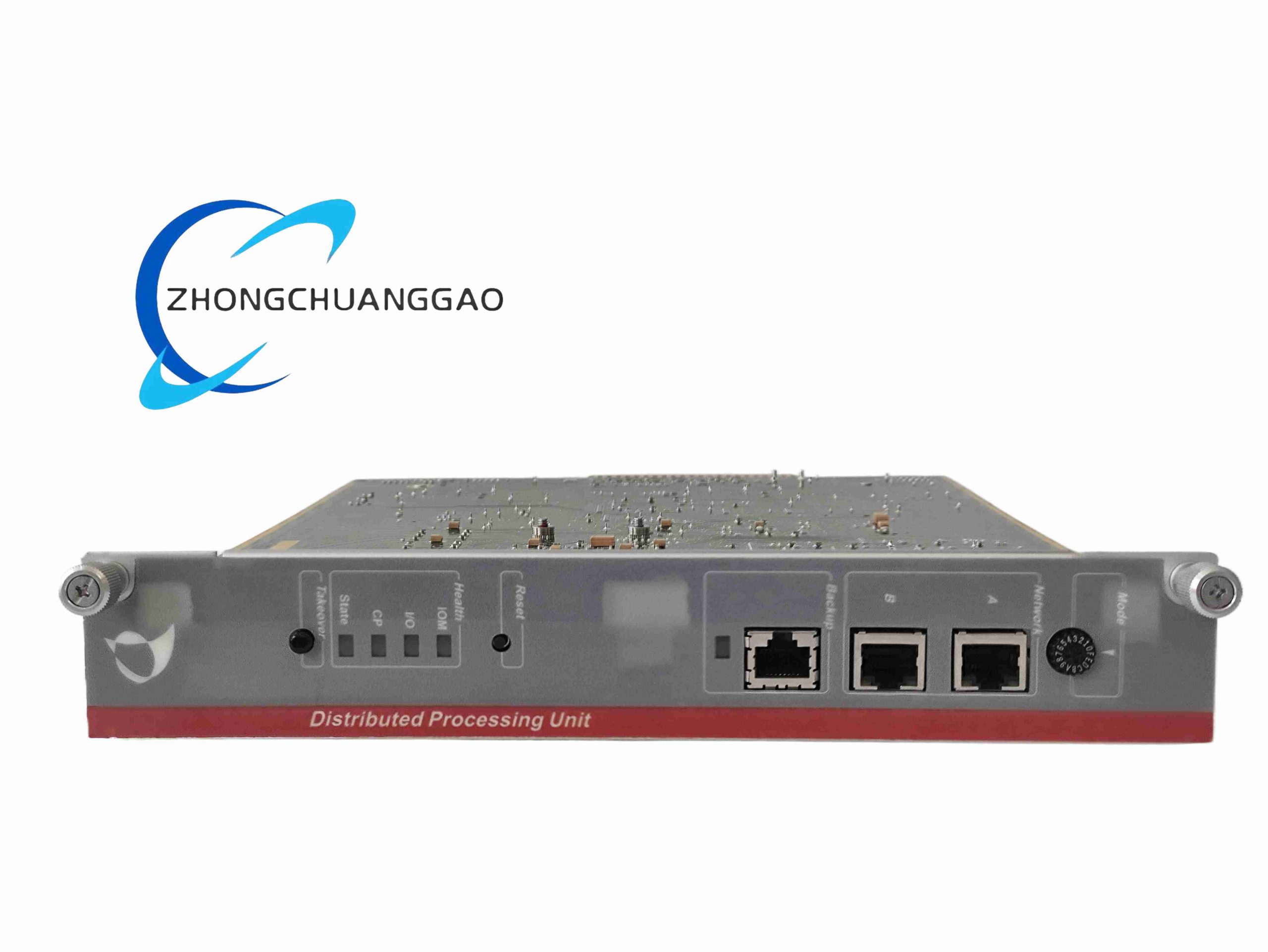
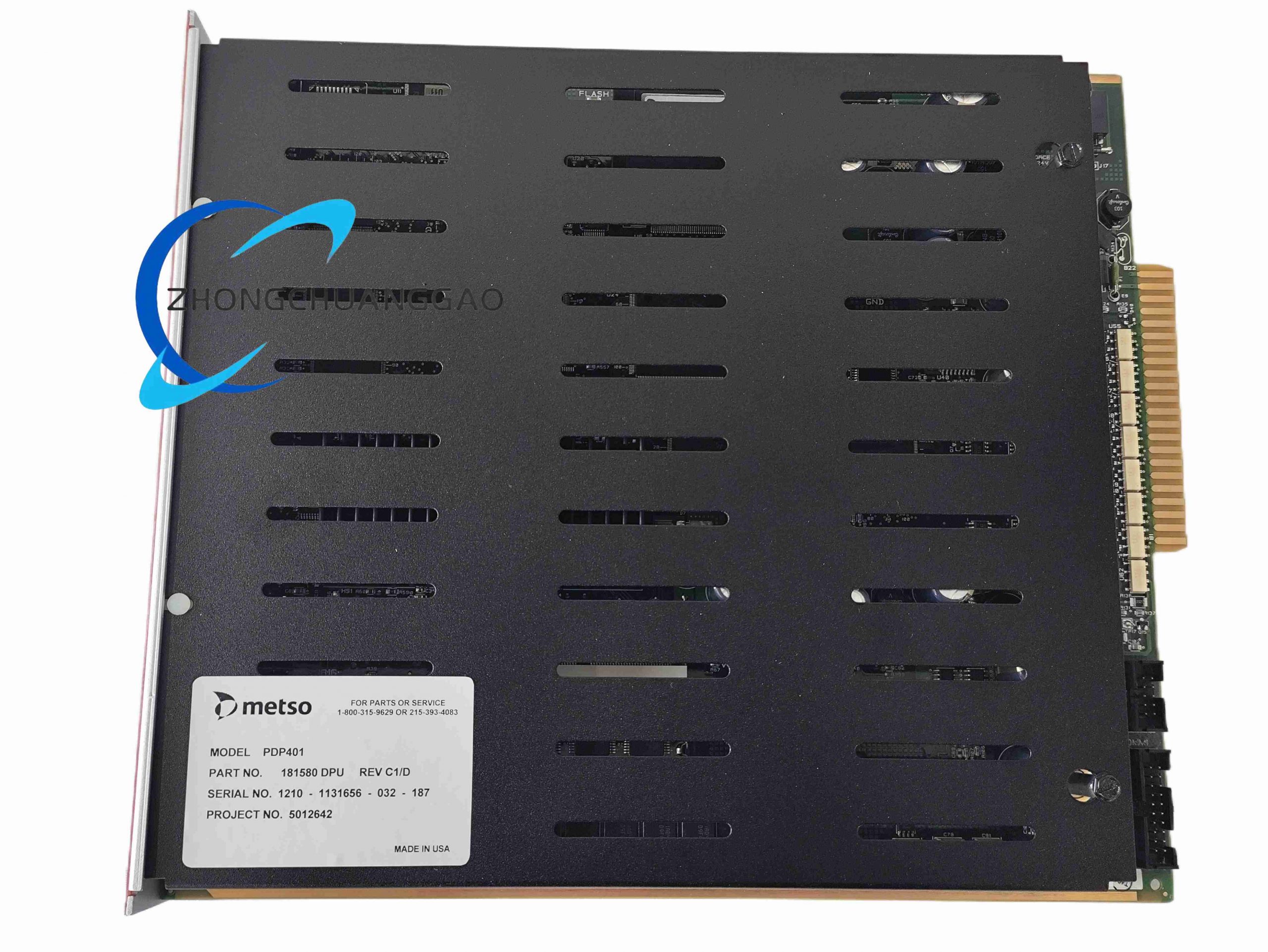
The PDP401 acts as the primary real-time computing engine of the Metso maxDNA distributed control system. It serves as the data bridge between field I/O modules, on-site sensors, actuators and upper-level SCADA, HMI, and supervisory control workstations. It executes closed-loop process control logic, high-speed signal acquisition, sequence-of-event logging, and real-time alarm management for heavy process industries. It adopts a compact single-slot rack-mounted architecture optimized for industrial cabinet environments with extreme temperature and electromagnetic interference conditions.
Description
Core Technical Specifications
- Processor: 32-bit real-time RISC microprocessor, 100MHz base clock frequency
- Operating System: Windows CE .NET real-time multi-task embedded OS, hard real-time 1ms task scheduling resolution
- Memory Configuration: 128MB SDRAM main memory, 256MB industrial-grade flash storage for firmware, logic programs and historical trend data
- Communication Interfaces: 3 x 10/100Mbps auto-negotiation RJ45 Ethernet ports (maxNET DCS backbone), RS232 diagnostic serial port, internal high-speed parallel backplane bus for I/O rack expansion
- Backplane Compatibility: Fits standard 8-slot maxPAC rack backplane, single slot horizontal insertion design
- Power Input: 24VDC nominal, allowable range 18–30VDC, maximum power consumption 30W
- Environmental Ratings: Operating temperature -20°C ~ +70°C; storage temperature -40°C ~ +85°C; relative humidity 5%–95% non-condensing
- Shock & Vibration Compliance: IEC 60068-2-6 vibration standard 5G (10–150Hz); IEC 60068-2-27 shock standard 15G operational, 30G transportation
- Certifications: CE, UL, FCC industrial control equipment certification
- Physical Dimensions: 300mm (depth) × 200mm (height) × 100mm (width); total weight 1.8kg
Function & Performance Features
- Real-time analog/digital I/O scanning with millisecond-level sampling cycle, compatible with all Metso maxDNA series I/O modules
- Built-in comprehensive process control algorithm library: PID cascade control, ratio control, feedforward regulation, dead band compensation, limit interlock logic
- High-precision SOE (Sequence of Event) recording with 1ms time stamp resolution for fault root cause analysis
- Continuous historical trend data buffering, supports long-term storage of flow, pressure, temperature, level measurement data
- Multi-level alarm classification: process deviation alarms, hardware fault alarms, communication loss alarms with latch & reset function
- Hot-swap capable module design; supports online replacement without full rack power shutdown
- Built-in hardware watchdog timer, automatic logic reset and fault isolation upon processor crash
- Full IEC 61131-3 programming standard support, compatible with Metso maxView configuration software for offline logic editing and online download
Working Principle
The PDP401 continuously polls connected I/O modules via the rack backplane to collect raw field signals (4–20mA analog, 24VDC digital switch status). The internal RISC processor executes pre-downloaded control function block logic to calculate output control values for valves, pumps, and regulators. Process data and alarm events are packaged via Ethernet and transmitted to upper HMI and data servers through the maxNET industrial network. All critical events are time-stamped and stored in local flash memory for offline retrieval when network disconnection occurs. The watchdog circuit monitors core processor operation; if program deadlock or communication timeout is detected, the unit automatically triggers soft reset and maintains safe fail-safe output states.
Material & Structural Composition
- Outer housing: Cold-rolled steel sheet with black anti-corrosion electrostatic spraying, slotted ventilation holes for passive convection cooling
- Core circuit board: FR4 high-Tg industrial PCB with gold-plated backplane edge connectors for low contact resistance and anti-oxidation
- Front panel: ABS high-temperature resistant engineering plastic, embedded status LED indicators for power, run, fault, Ethernet link activity
- Internal components: Industrial-grade solid-state capacitors, wide-temperature range crystal oscillators, isolated Ethernet transformers for EMC noise suppression
- Fixing hardware: Stainless steel locking latches for rack insertion and anti-loosening M3 mounting screws
Installation Requirements
- Must be installed horizontally inside standard industrial control cabinet on maxPAC series backplane rack, vertical mounting strictly prohibited
- Maintain minimum 50mm top and bottom clearance between the module and cabinet walls for heat dissipation; do not block ventilation slots
- Separate power wiring and signal wiring into dedicated cable ducts to reduce electromagnetic interference
- Connect dedicated 24VDC redundant power supply; use shielded twisted-pair Ethernet cables with 360° metal shield grounding
- All cabinet metal frames and module housing must connect to equipotential protective earth ground with copper ground wire ≥2.5mm² cross-section
- Allow 10-minute power-on preheating before downloading control logic for stable temperature operation
Typical Application Scenarios
- Mineral processing: Ore crushing, flotation, grinding process automation control
- Pulp & paper industry: Pulp cooking, paper machine speed and thickness closed-loop control
- Power plant auxiliary systems: Boiler water supply, flue gas desulfurization, ash handling process monitoring
- Water treatment plants: Raw water filtration, sewage biochemical treatment, chemical dosing automatic regulation
- Oil & gas midstream facilities: Pipeline pressure flow control, storage tank level monitoring
Mandatory Operation & Maintenance Precautions
- Static discharge protection wristband must be worn during module disassembly, installation, or firmware upgrade to prevent PCB chip burnout
- Avoid operating the unit in environments with corrosive gas, conductive dust, or continuous water mist condensation
- Do not plug/unplug Ethernet or backplane connectors under live power conditions to avoid communication chip damage
- Regularly clean ventilation slits every 6 months to prevent dust accumulation leading to overheating shutdown
- Backup control logic and historical configuration data to external storage before firmware version upgrade
- If long-term power outage exceeds 30 days, re-calibrate analog signal sampling channels after power restoration
- When communication fault occurs, first inspect shield grounding integrity and Ethernet cable continuity before replacing the PDP401 module
Reviews
There are no reviews yet.