
Description
Product Overview
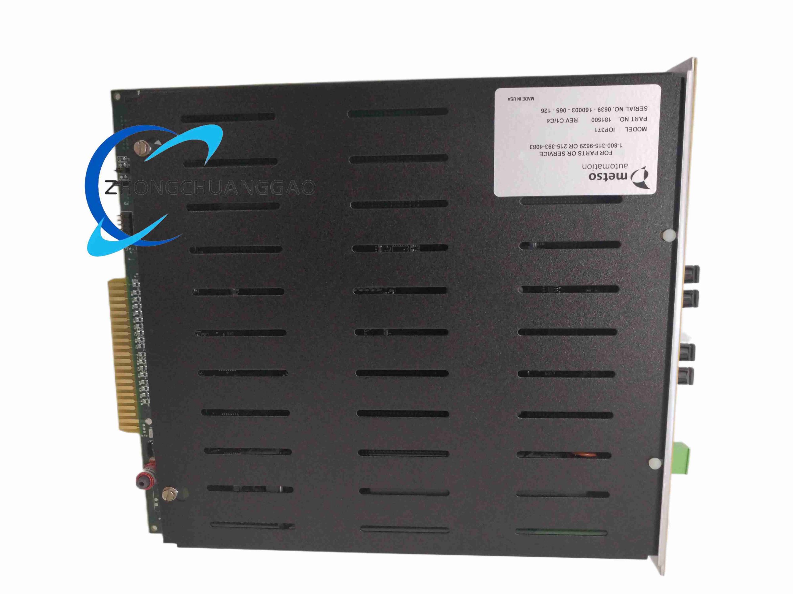
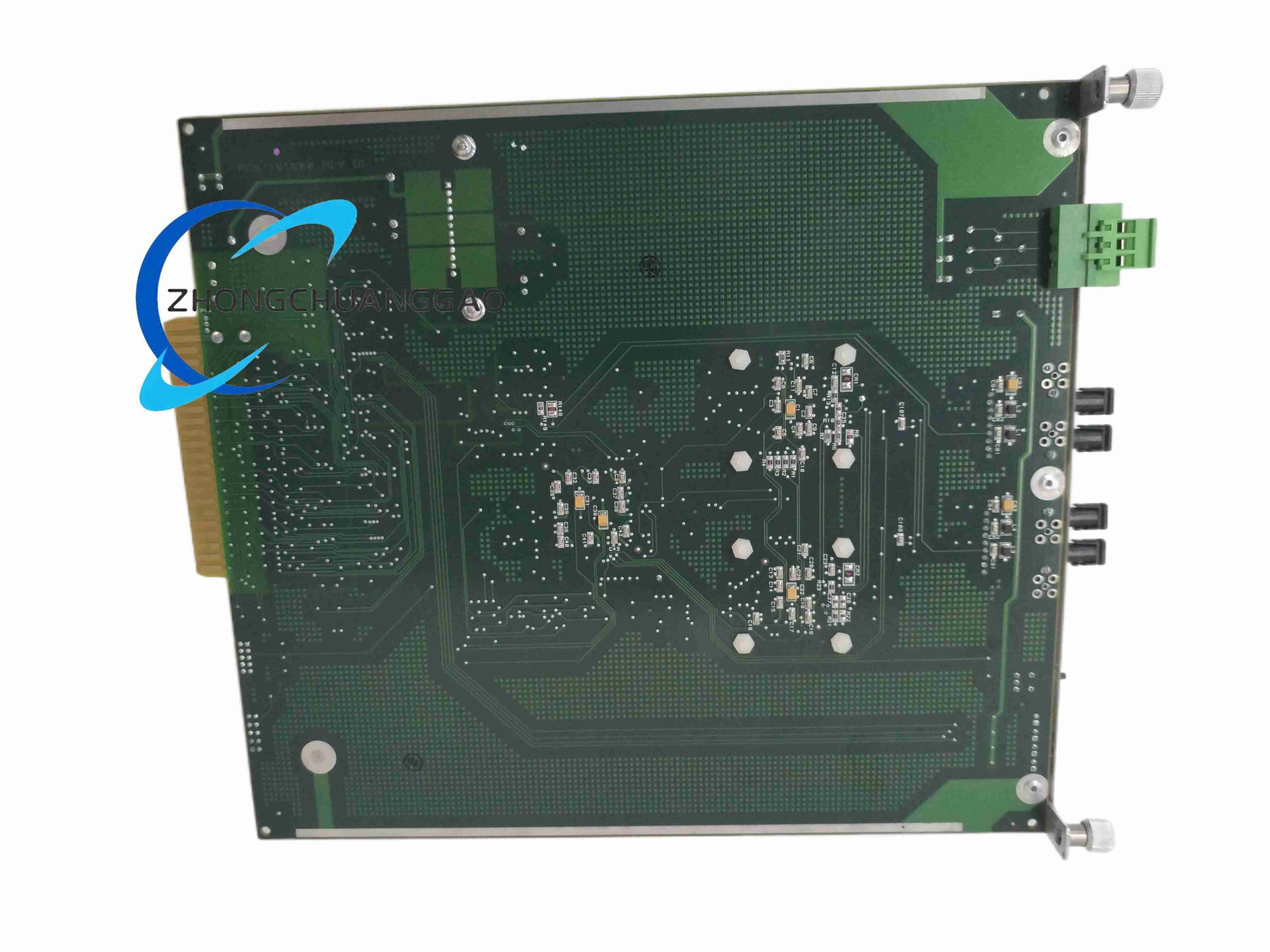
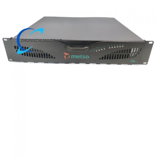
This module is dedicated bus extension hardware for Metso DNA DCS platform, realizing long-distance transmission of proprietary DCS I/O backplane bus signals between central control rack and remote field I/O racks, breaking the 30 m limit of standard DCS backplane wiring distance, supporting multi-node remote I/O rack cascading, maintaining complete real-time signal synchronization and data integrity in mineral processing, metallurgy long workshop control environments.
Technical Core Specifications
- Bus Communication Parameters
- Native bus protocol: Metso DNA proprietary I/O backplane bus
- Communication baud rate: 1 Mbps ~ 10 Mbps automatic adaptive
- Maximum extension transmission distance: 1000 m (twisted pair cable), 2000 m (single-mode optical fiber)
- Single module expandable remote I/O rack quantity: 8–16 cascaded nodes
- Isolation Performance
- Bus side and field remote side galvanic isolation voltage: 2500 Vrms
- Power Supply Specification
- Power input: 24 V DC backplane bus power supply
- Static power consumption: 5 W low energy loss design
- Mechanical Dimensions & Weight
- Overall size: 120 mm (L) × 90 mm (W) × 45 mm (H)
- Net weight: 0.2 kg
- Mounting form: 35 mm DIN rail cabinet mounting
- Environmental Rating
- Operating temperature: −20 °C ~ +70 °C
- Relative humidity: 5%–95% non-condensing
- Protection class: IP20
Functional Features
- Dual media support: twisted copper pair and single-mode fiber optical transmission interface interchangeable via pluggable interface adapter
- Real-time bus signal synchronization correction circuit, eliminating transmission delay deviation between multi-node remote racks
- Automatic bus link fault diagnosis, front panel LED indicator for link breakage, short circuit and communication timeout
- Built-in signal surge suppression circuit for field remote cable lightning surge protection
- Plug-and-play cascading without complex software address configuration, automatic node identification
- Bidirectional signal amplification and reshaping to eliminate long-distance cable signal attenuation distortion
Working Principle
Metso DNA central rack CPU backplane I/O bus signal enters IOP371 local bus interface, processed by signal shaping and isolation circuit, converted to differential twisted pair or optical signal for long-distance transmission to remote field IOP371 slave module. Slave module restores original DCS backplane bus signal and outputs to remote I/O rack backplane, realizing transparent bus data exchange between central control unit and remote analog/digital I/O modules without protocol conversion delay.
Material & Structural Composition
- PCB: Miniaturized high-density FR4 circuit board with surface mount components
- Shell: Lightweight black flame retardant PC plastic integrated enclosure
- Transmission interface: Industrial grade fiber SC adapter and screw-type twisted pair terminal block
- Internal core components: Bus signal isolation optocoupler, signal reshaping amplifier chip, lightning protection TVS diode array
Advantage Highlights
- Ultra-low power consumption reduces cabinet cooling load for long-term continuous operation
- Fiber transmission completely eliminates electromagnetic interference in mineral processing high-vibration, high-magnetic field workshop
- Plug-and-play cascading greatly shortens DCS remote I/O system construction and debugging cycle
- Compact small volume saves cabinet installation space compared with third-party bus repeaters
- Full compatibility with all Metso DNA series I/O racks without system firmware upgrade
Applicable Industries
Mining mineral flotation control, iron & steel metallurgy sintering workshop, cement raw material processing plant, non-ferrous metal smelting, aggregate crushing production line, long-distance water treatment plant distributed control
Installation Mandatory Requirements
- Install inside sealed control cabinet, avoid direct dust and mineral powder erosion on module surface
- Optical fiber cable bending radius must maintain ≥30 mm to prevent optical signal attenuation
- Twisted pair communication cable must use industrial shielded differential pair cable, shielding grounded at remote cabinet side only
- Each cascading branch total cable length cannot exceed maximum rated transmission distance of module
Operation & Maintenance Precautions
- Inspect optical fiber interface dust contamination every 6 months, clean only with professional fiber wiping paper
- Do not hot-plug twisted pair bus terminals under system running state to avoid bus communication collapse
- Avoid installing module near high-power frequency converters and heavy-duty motor starters without metal shielding partition
- Replace module when communication fault LED keeps steady bright after cable full inspection
Reviews
There are no reviews yet.